E1/E20/E2/E2 Lite Additional Document 2. Designing the User System
R20UT1994EJ0910 Rev.9.10 Page 22 of 59
Oct.06.23
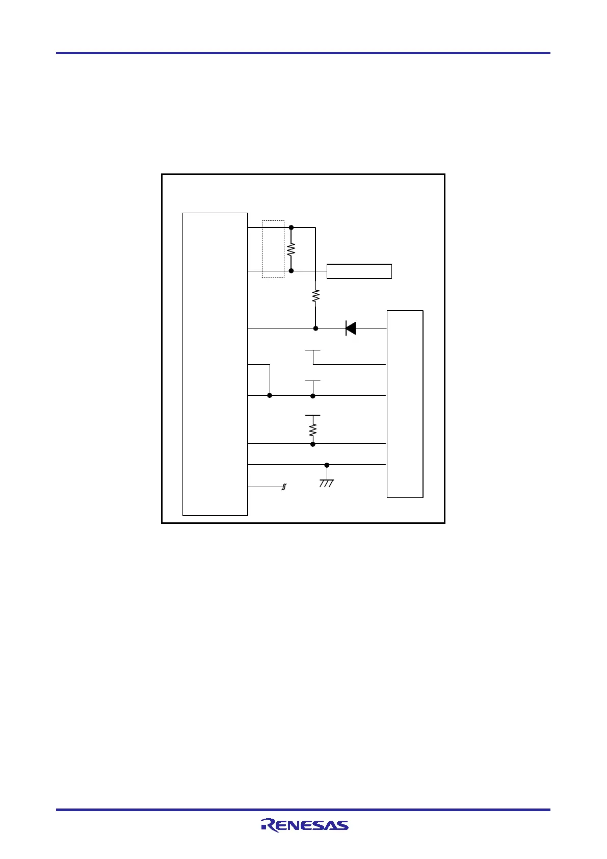
2.4.3 Connection between the 14-Pin Connector and the RL78 Family MCU (Only the RL78/I1C)
The following shows a recommended circuit for connection between the 14-pin connector and the RL78
family MCU (only the RL78/I1C).
Figure 2-7 shows the case when the battery backup function is in use.
Figure 2-8 shows the case when the battery backup function is not in use.
8
VSS
VDD
9
2,12,14
1,3,7,11
5 TOOL0
TOOL0
EMVDD
VDD
VSS
R.F.U
6
10,13
RESET_IN
RESET_OUT
RESET#
4
RSTPU
EVDD
VDD
EVDD
EVDD
470 to 510 Ω
1 kΩ
1 kΩ
Note 1
Note 2
14-pin
2.54-mm pitch
connector
Note 3
Note 3
Note 4
Reset circuit
Note 5
Note 3 Note 6
MCU
Note 3
Note 7
Note 8
Note 9
Note 9
Figure 2-7 Example of Connection when the Battery Backup Function of the RL78/I1C is in Use

 Loading...


