E1/E20/E2/E2 Lite Additional Document 2. Designing the User System
R20UT1994EJ0910 Rev.9.10 Page 31 of 59
Oct.06.23
2.6 Internal Circuits of the Emulator
2.6.1 Internal Circuits of the E1 (when the RL78 Family is Connected)
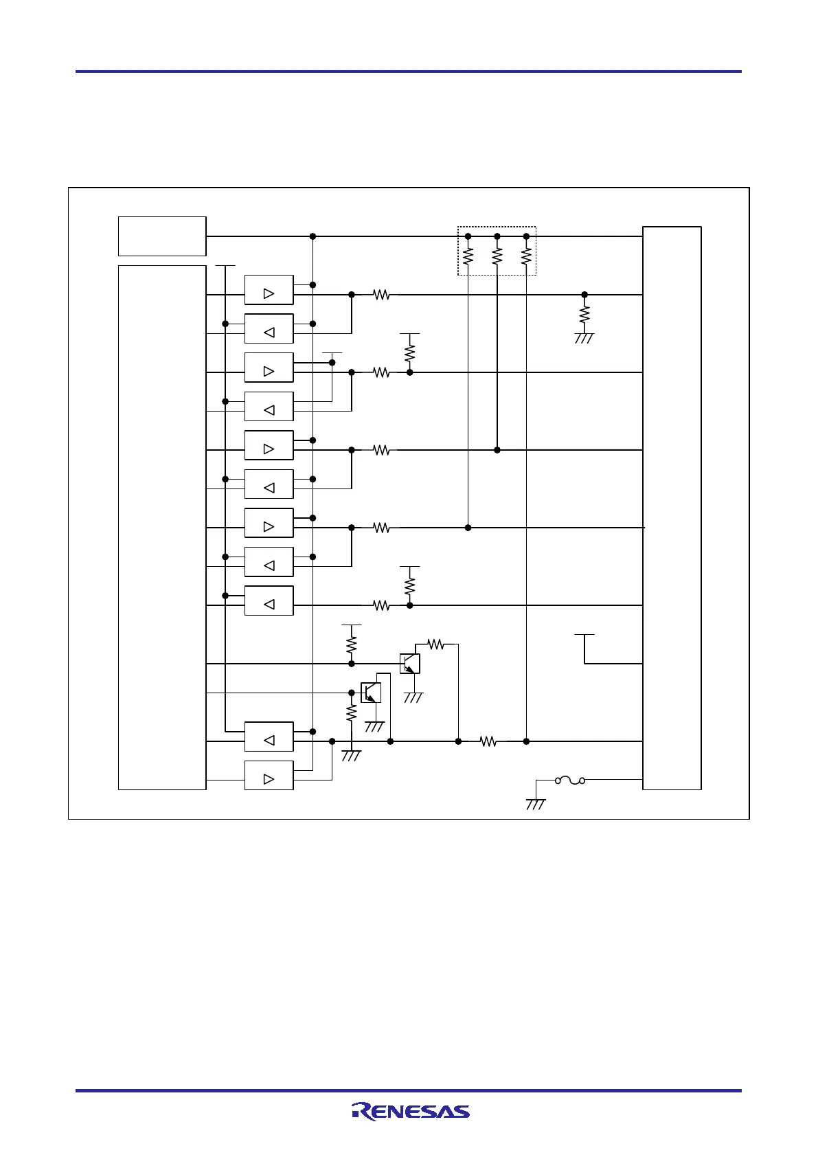
Figure 2-16 shows the internal circuits of the E1 with the RL78 family connected.
Emulator
cont rol
circuit
User-side
connector
100 kΩ
RSTPU
VDD
4
8
22 Ω
74 LV C125
74 LV C8T24 5
3.3 V
EMVDD
TOOL0
5
74 LV C125
EMVDD
74 LV C125
74 LV C8T24 5
6
RESET_IN
74 LV C125
74 LV C8T24 5
22 Ω
10
RESET_OUT
3.3 V
74 LV C125
22 Ω 100 kΩ
GND
14
3.3 V
74 LV C8T24 5
13
RESET_OUT
22 Ω
470 Ω
Sel f-recovering
fuse
2,12
GND
Po w er-supply circuit
(only for use in the mode to
supply power to the user
sy ste m)
EMVDD
EMVDD
9
22 Ω
22 Ω
74 LV C2T24 5
100 kΩ
74 LV C125
100 kΩ × 3
Figure 2-16 Internal Circuit of the E1 (when the RL78 Family is Connected)

 Loading...


