E1/E20/E2/E2 Lite Additional Document 2. Designing the User System
R20UT1994EJ0910 Rev.9.10 Page 13 of 59
Oct.06.23
2. Designing the User System
2.1 Connecting the E1/E20/E2/E2 Lite to the User System
To connect the E1/E20/E2/E2 Lite to the user system, a connector for the user system interface cable must
be mounted on the user system.
When designing the user system, read this section of this manual and the hardware manual for the MCU in
use.
2.2 Installing the Connector on the User System
Table 2-1 shows the recommended connectors for the E1/E20/E2/E2 Lite.
Table 2-1 Recommended Connectors
connector
14-pin straight type (Japan)
2514-6002 3M Limited 14-pin straight type (other countries)
Note: Connection to the 38-pin connector of the E20 is not supported. To use the E20, use the 38-pin to 14-pin
conversion adapter that comes with the E20 for connection to the 14-pin connector on the user system.
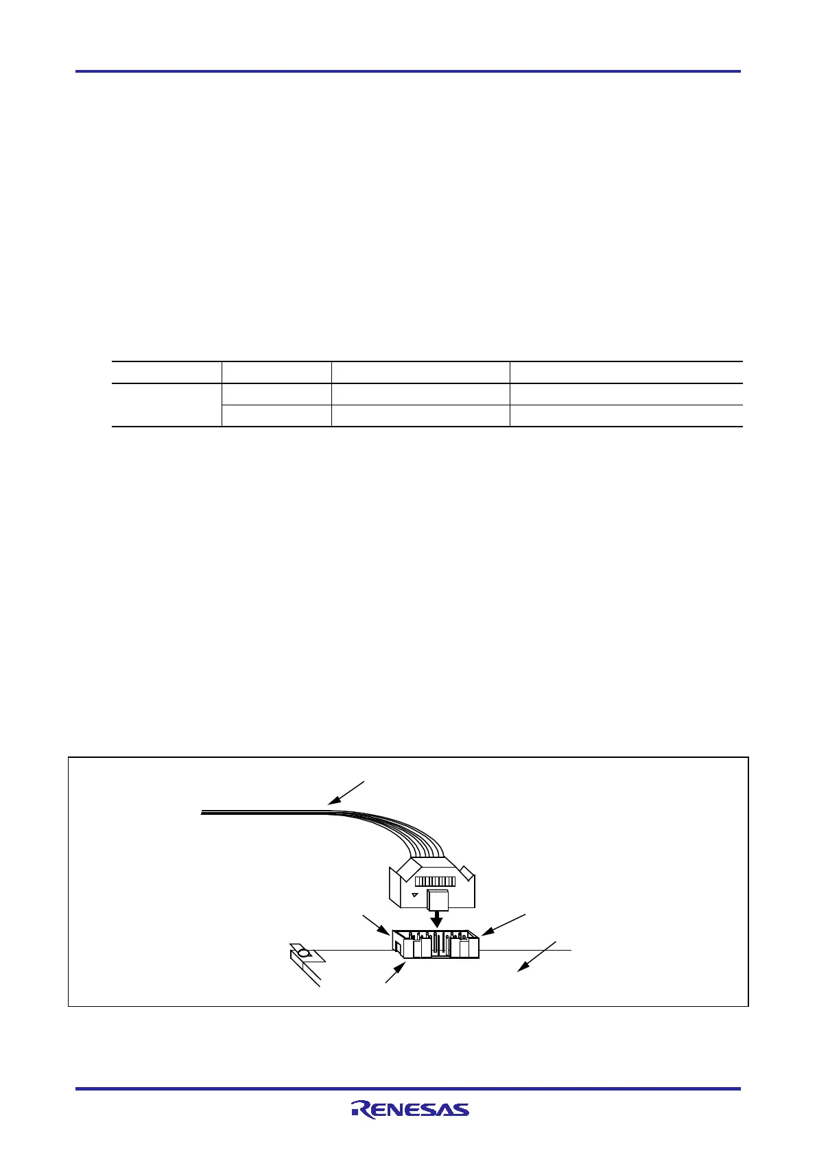
2.2.1 Connecting the User System Interface Cable to the 14-Pin Connector
The following figures show how to connect the user system interface cable to the 14-pin connector of each
emulator.
E1/E2 Lite: Figure 2-1
(Connecting the User System Interface Cable to the 14-Pin Connector of the E1/E2 Lite Emulator)
E20: Figure 2-2
(Connecting the User System Interface Cable to the 14-Pin Connector of the E20 Emulator)
E2: Figure 2-3
(Connecting the User System Interface Cable to the 14-Pin Connector of the E2 Emulator)
Figure 2-1 Connecting the User System Interface Cable to the 14-Pin Connector of the E1/E2 Lite
Emulator
14-p
in u
ser-
system interface cable
14
-pin connector
7614-6002 or
2514-6002
User system
Pin 1
Pin 2

 Loading...


