E1/E20/E2/E2 Lite Additional Document 2. Designing the User System
R20UT1994EJ0910 Rev.9.10 Page 14 of 59
Oct.06.23
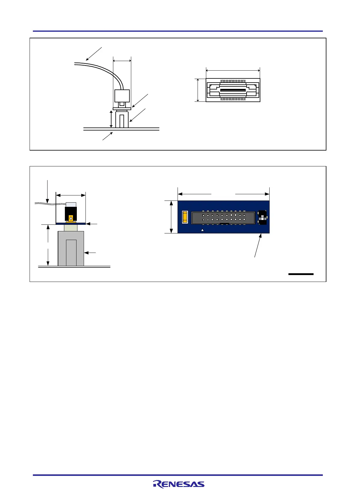
Figure 2-2 Connecting the User System Interface Cable to the 14-Pin Connector of the E20 Emulator
20-pin (1.27-mm pin spacing
) user-
system
interface cable
13 mm
10
.
5 mm
User system
14-pin (2.54-
mm pin spacing)
connector
7614-6002 or 2514
-6002
20
-pin
(1
.27-mm pin
spacing) to 14-pin
(2.54-mm pin spacing)
connector conversion
adapter
10
.5 mm
20-pin (1.27-mm pin spacing)
to 14-pin
(2.54-mm pin spacing) connector
conversion adapte
r (top view
)
29.0 mm
1
3
Set the switch to position
"3".
Figure 2-3 Connecting the User System Interface Cable to the 14-Pin Connector of the E2 Emulator
3
8
-
p
i
n
t
o
1
4
-
p
i
n
c
o
n
v
e
r
s
i
o
n
a
d
a
p
t
e
r
(t
o
p v
ie
w
)
R0E000200CKA00
(
i
n
c
l
u
d
e
i
n
t
h
e
E
2
0
p
a
c
k
a
g
e
)
10 mm
User system
3
8
-p
in
u
se
r-
s
ys
t
e
m
i
n
t
e
r
f
a
c
e
c
a
b
l
e
26.2 mm
9.4 mm
38
-p
i
n t
o 1
4
-p
i
n
co
nv
e
rs
io
n
ad
a
pt
er
9
.4
m
m
1
4-
pi
n
co
nn
e
ct
or
7
6
1
4
-
6
0
0
2
o
r
2
51
4
-6
00
2

 Loading...


