RL78/G13 CHAPTER 6 TIMER ARRAY UNIT
R01UH0146EJ0100 Rev.1.00 329
Sep 22, 2011
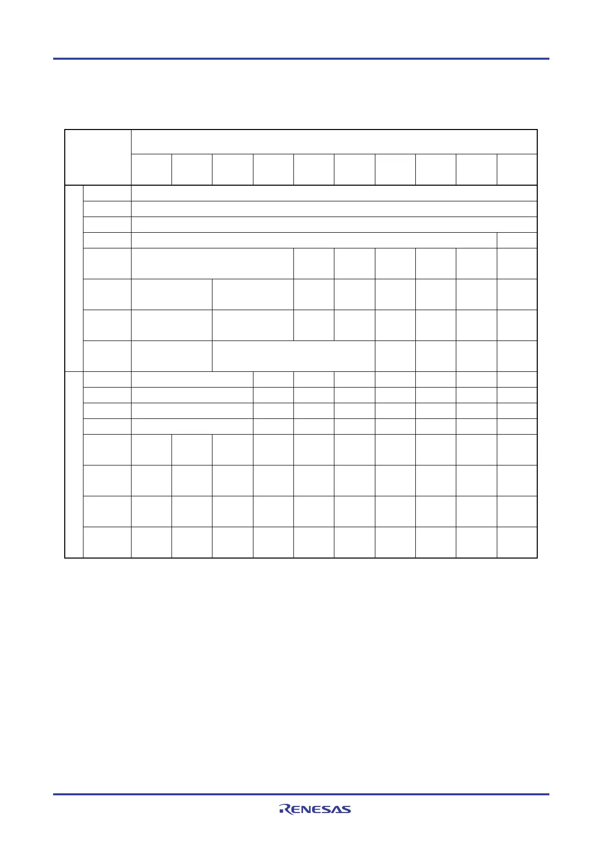
The presence or absence of timer I/O pins in each timer array unit channel depends on the product.
Table 6-2. Timer I/O Pins provided in Each Product
I/O Pins of Each Product
Timer array unit
channels
128-pin 100-pin 80-pin 64-pin 52-pin 44, 48-pin 40-pin 30, 32,
36-pin
24, 25-
pin
20-pin
Channel 0 P00/TI00, P01/TO00
Channel 1 P16/TI01/TO01
Channel 2 P17/TI02/TO02
Note
Channel 3 P31/TI03/TO03
Note
−
Channel 4
P42/TI04/TO04
(P13)
(P13) (P13) (P13) (P13) − −
Channel 5
P46/TI05/TO05
(P12)
P05/TI05/TO05
(P12)
(P12) (P12) (P12) (P12) − −
Channel 6
P102/TI06/TO06
(P11)
P06/TI06/TO06
(P11)
(P11) (P11) (P11) (P11) − −
Unit 0
Channel 7
P145/TI07/TO07
(P10)
P41/TI07/TO07
(P10)
(P10) (P10) − −
Channel 0 P64/TI10/TO10 × × × × × × ×
Channel 1 P65/TI11/TO11 × × × × × × ×
Channel 2 P66/TI12/TO12 × × × × × × ×
Channel 3 P67/TI13/TO13 × × × × × × ×
Channel 4
P103/TI14
/TO14
× × × × × × × × ×
Channel 5
P104/TI15
/TO15
× × × × × × × × ×
Channel 6
P105/TI16
/TO16
× × × × × × × × ×
Unit 1
Channel 7
P106/TI17
/TO17
× × × × × × × ×
Note For 30- to 128-pin products, channel 2 and 3 can be set P15 and P14 with setting the bit 0 of the peripheral I/O
redirection register (PIOR) to “1”.
Remarks 1. When timer input and timer output are shared by the same pin, either only timer input or only timer output
can be used.
2. −: There is no timer I/O pin, but the channel is available. (However, the channel can only be used as an
interval timer.)
×: The channel is not available.
3. “(P1x)” indicates an alternate port when the bit 0 of the peripheral I/O redirection register (PIOR) is set to “1”.
Figures 6-1 and 6-2 show the block diagrams of the timer array unit.
<R>

 Loading...


