E1/E20/E2/E2 Lite Additional Document 2. Designing the User System
R20UT1994EJ0910 Rev.9.10 Page 37 of 59
Oct.06.23
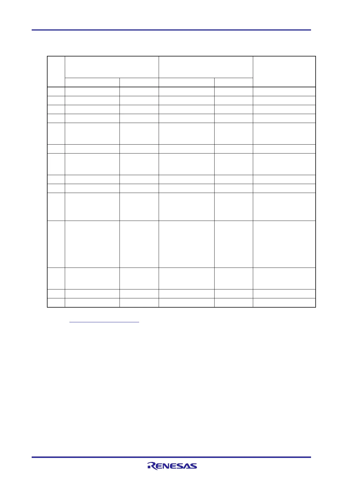
Table 2-4 Connector Pin Assignments when the Small Connector Conversion Adapter for the E1 is
Used
Pin
No.
RL78 family MCUs in general
Only for RL78/G11, RL78/I1C, and
20- and 24-pin versions of
RL78/G12
Note
1 GND *3 - GND *3 -
-
-
3 VDD - VDD -
-
-
5 RESET_OUT *4 Input RESET_OUT *4 Input
This pin is used to
output a reset signal to
the target device.
-
-
7 RESET_OUT *4 Input RESET_OUT *4 Input
This pin is used to
output a reset signal to
the target device.
-
-
9 R.F.U *5 - R.F.U *5 -
transmit
command/data to the
target device.
11 R.F.U *5 - RSTPU Input
This pin is used to pull
up the reset line (only
when the RL78/G11,
the RL78/I1C, and 20-
and 24-pin versions of
the RL78/G12 are in
use).
input a reset signal
from the user system.
13 EMVDD *6 - EMVDD *6 -
-
-
For details on the programming software, refer to the following.
https://www.renesas.com/RFP
“Input” refers to input from the emulator to the user system and “output” refers to output from the user
system to the emulator.
Securely connect pins 1, 6, and 14 of the connector to GND of the user system. These pins are used for
electrical grounding as well as for monitoring of connection with the user system by the E1/E20/E2 Lite.
Securely connect both pin 5 and pin 7.
This pin is reserved. Perform the open processing.
Connect the driving power supply for the TOOL0 pin to EMVDD.
Please connect VDD when the MCU does not have power supplies other than VDD such as EVDD.
The E2 Lite only supports a single power supply. If you are using an MCU that requires two or more
power supplies with the E2 Lite, use a power supply other than VDD, such as EVDD, which has the same
voltage as VDD.

 Loading...


