RL78/G13 CHAPTER 6 TIMER ARRAY UNIT
R01UH0146EJ0100 Rev.1.00 366
Sep 22, 2011
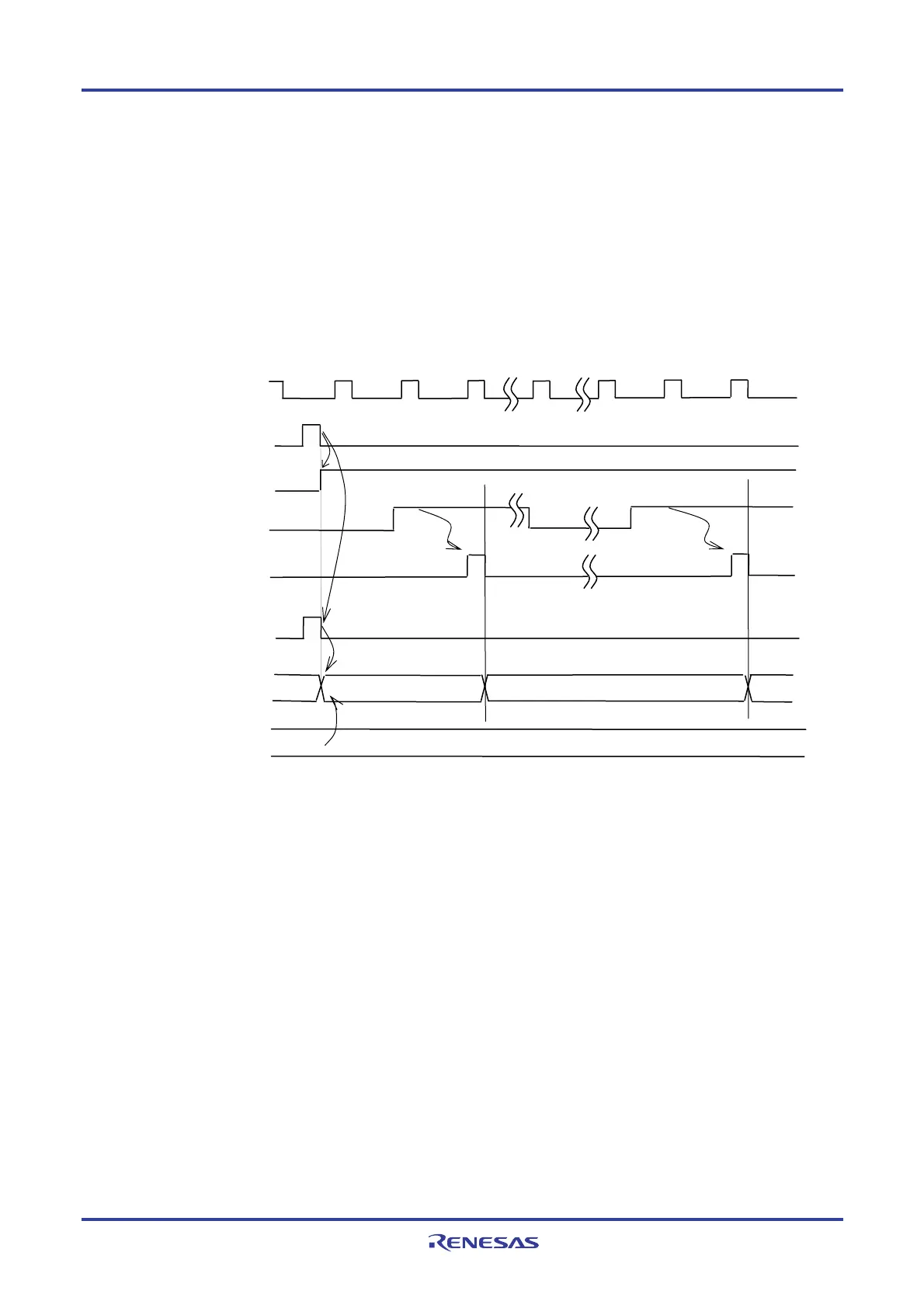
(b) Start timing in event counter mode
<1> Timer count register mn (TCRmn) holds its initial value while operation is stopped (TEmn = 0).
<2> Operation is enabled (TEmn = 1) by writing 1 to the TSmn bit.
<3> As soon as 1 has been written to the TSmn bit and 1 has been set to the TEmn bit, the value of timer data
register mn (TDRmn) is loaded to the TCRmn register to start counting.
<4> After that, the TCRmn register value is counted down according to the count clock of the valid edge of the
TImn input .
Figure 6-24. Start Timing (In Event Counter Mode)
Remark The timing is shown in Figure 6-24 indicates while the noise filter is not used. By making the noise filter
on-state, the edge detection becomes 2 f
MCK cycles (it sums up to 3 to 4 cycles) later than the normal
cycle of TImn input.
fMCK
TSmn(Write)
TEmn
TImn input
<1>
<2>
Count clock
Edge detection
Edge detection
<4>
m
TCRmn
Initial
value
m
m−1
m−2
TDRmn
<3>
Start trigger
detection signal
<1>
<3>

 Loading...


