RL78/G13 CHAPTER 6 TIMER ARRAY UNIT
R01UH0146EJ0100 Rev.1.00 398
Sep 22, 2011
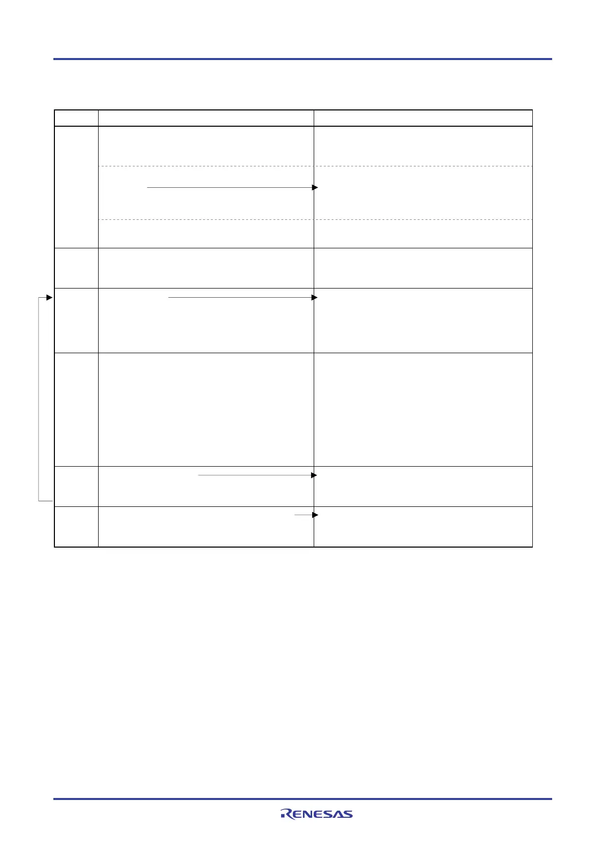
Figure 6-52. Operation Procedure When Input Pulse Interval Measurement Function Is Used
Software Operation Hardware Status
Power-off status
(Clock supply is stopped and writing to each register is
disabled.)
Sets the TAUmEN bit of peripheral enable register 0
(PER0) to 1.
Power-on status. Each channel stops operating.
(Clock supply is started and writing to each register is
enabled.)
TAU
default
setting
Sets timer clock select register m (TPSm).
Determines clock frequencies of CKm0 and CKm1.
Channel
default
setting
Sets timer mode register mn (TMRmn) (determines
operation mode of channel).
Channel stops operating.
(Clock is supplied and some power is consumed.)
Operation
start
Sets TSmn bit to 1.
The TSmn bit automatically returns to 0 because it is a
trigger bit.
TEmn = 1, and count operation starts.
Timer count register mn (TCRmn) is cleared to 0000H
at the count clock input.
When the MDmn0 bit of the TMRmn register is 1,
INTTMmn is generated.
During
operation
Set values of only the CISmn1 and CISmn0 bits of the
TMRmn register can be changed.
The TDRmn register can always be read.
The TCRmn register can always be read.
The TSRmn register can always be read.
Set values of the TOMmn, TOLmn, TOmn, and TOEmn
bits cannot be changed.
Counter (TCRmn) counts up from 0000H. When the TImn
pin input valid edge is detected, the count value is
transferred (captured) to timer data register mn (TDRmn).
At the same time, the TCRmn register is cleared to
0000H, and the INTTMmn signal is generated.
If an overflow occurs at this time, the OVF bit of timer
status register mn (TSRmn) is set; if an overflow does not
occur, the OVF bit is cleared.
After that, the above operation is repeated.
Operation
stop
The TTmn bit is set to 1.
The TTmn bit automatically returns to 0 because it is a
trigger bit.
TEmn = 0, and count operation stops.
The TCRmn register holds count value and stops.
The OVF bit of the TSRmn register is also held.
TAU
stop
The TAUmEN bit of the PER0 register is cleared to 0.
Power-off status
All circuits are initialized and SFR of each channel is
also initialized.
Remark m: Unit number (m = 0, 1), n: Channel number (n = 0 to 7)
Operation is resumed.

 Loading...


