RL78/G13 CHAPTER 8 INTERVAL TIMER
R01UH0146EJ0100 Rev.1.00 460
Sep 22, 2011
(3) Interval timer control register (ITMC)
This register is used to set up the starting and stopping of the interval timer operation and to specify the timer
compare value.
The ITMC register can be set by a 16-bit memory manipulation instruction.
Reset signal generation clears this register to 0FFFH.
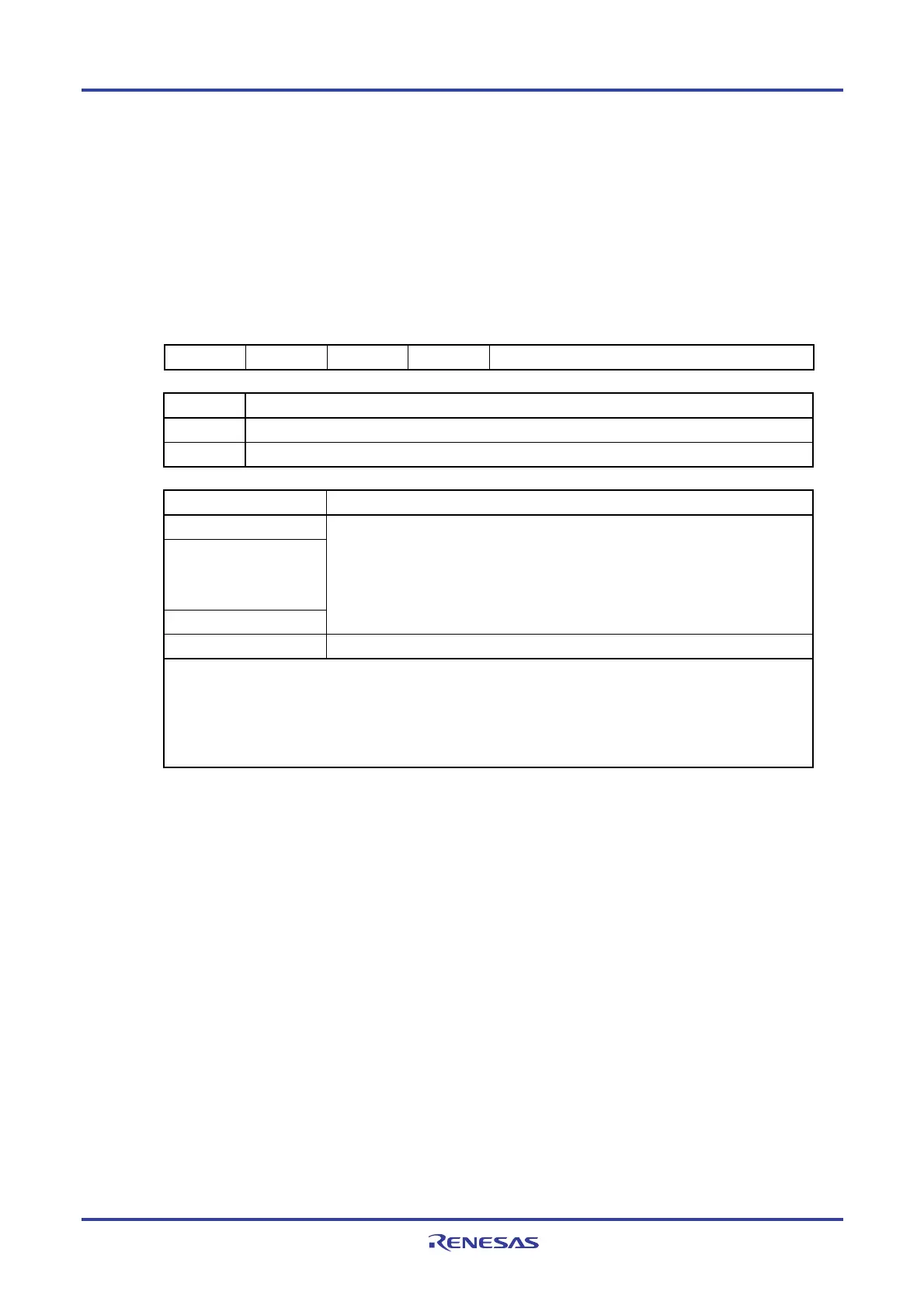
Figure 8-4. Format of Interval Timer Control Register (ITMC)
Address: FFF90H After reset: 0FFFH R/W
Symbol 15 14 13 12 11 to 0
ITMC RINTE 0 0 0 ITCMP11 to ITCMP0
RINTE Interval timer operation control
0 Count operation stopped (count clear)
1 Count operation started
ITCMP11 to ITCMP0 Specification of the interval timer compare value
001H
•
•
•
FFFH
These bits generate an interrupt at the fixed cycle (count clock cycles x (ITCMP
setting + 1)).
000H Setting prohibit
Example interrupt cycles when 001H or FFFH is specified for ITCMP11 to ITCMP0
• ITCMP11 to ITCMP0 = 001H, count clock: when f
SUB = 32.768 kHz
1/32.768 [kHz] × (1 + 1) = 0.06103515625 [ms] ≅ 61.03 [
μ
s]
• ITCMP11 to ITCMP0 = FFFH, count clock: when f
SUB = 32.768 kHz
1/32.768 [kHz] × (4095 + 1) = 125 [ms]
Cautions 1. Before changing the RINTE bit from 1 to 0, use the interrupt mask flag register to disable the
INTIT interrupt servicing. When the operation starts (from 0 to 1) again, clear the ITIF flag,
and then enable the interrupt servicing.
2. The value read from the RINTE bit is applied one count clock cycle after setting the RINTE bit.
3. Only change the setting of the ITCMP11 to ITCMP0 bits when RINTE = 0.
However, it is possible to change the settings of the ITCMP11 to ITCMP0 bits at the same time
as when changing RINTE from 0 to 1 or 1 to 0.
<R>

 Loading...


