RL78/G13 CHAPTER 12 SERIAL ARRAY UNIT
R01UH0146EJ0100 Rev.1.00 560
Sep 22, 2011
(10) Serial channel enable status register m (SEm)
The SEm register indicates whether data transmission/reception operation of each channel is enabled or stopped.
When 1 is written a bit of serial channel start register m (SSm), the corresponding bit of this register is set to 1.
When 1 is written a bit of serial channel stop register m (STm), the corresponding bit is cleared to 0.
Channel n that is enabled to operate cannot rewrite by software the value of the CKOmn bit (serial clock output of
channel n) of serial output register m (SOm) to be described below, and a value reflected by a communication
operation is output from the serial clock pin.
Channel n that stops operation can set the value of the CKOmn bit of the SOm register by software and output its
value from the serial clock pin. In this way, any waveform, such as that of a start condition/stop condition, can be
created by software.
The SEm register can be read by a 16-bit memory manipulation instruction.
The lower 8 bits of the SEm register can be set with a 1-bit or 8-bit memory manipulation instruction with SEmL.
Reset signal generation clears the SEm register to 0000H.
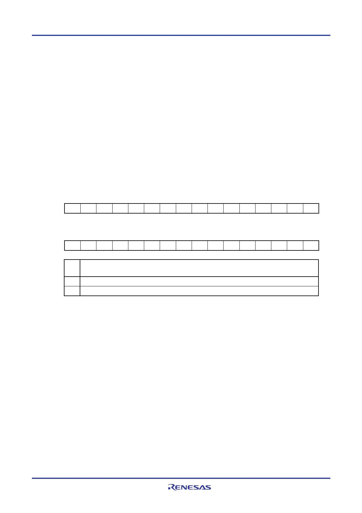
Figure 12-14. Format of Serial Channel Enable Status Register m (SEm)
Address: F0120H, F0121H (SE0) After reset: 0000H R
Symbol 15 14 13 12 11 10 9 8 7 6 5 4 3 2 1 0
SE0 0 0 0 0 0 0 0 0 0 0 0 0 SE03 SE02 SE01 SE00
Address: F0160H, F0161H (SE1) After reset: 0000H R
Symbol 15 14 13 12 11 10 9 8 7 6 5 4 3 2 1 0
SE1 0 0 0 0 0 0 0 0 0 0 0 0 SE13 SE12 SE11 SE10
SEm
n
Indication of operation enable/stop status of channel n
0 Operation stops
1 Operation is enabled.
Remark m: Unit number (m = 0, 1), n: Channel number (n = 0 to 3)

 Loading...


