RL78/G13 CHAPTER 12 SERIAL ARRAY UNIT
R01UH0146EJ0100 Rev.1.00 630
Sep 22, 2011
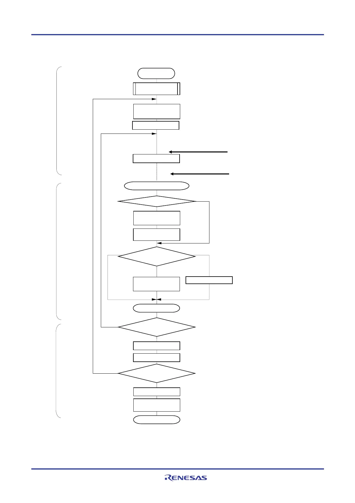
Figure 12-71. Flowchart of Slave Transmission/Reception (in Continuous Transmission/Reception Mode)
Setting
transmission/reception data
Read receive data to SIOp
(=SDRmn[7:0])
Write STmn bit to 1
For the initial setting, refer to Figure 12-59
(Select buffer empty interrupt)
SAU default setting
No
Yes
No
= 1
End of communication
Yes
Yes
No
Communication
continued?
Yes
Clear SAUmEN bit of the
PER0 register to 0
Number of communication
data
?
Disable interrupt (MASK)
BFFmn = 1?
<3>
<5>
<6>
<7>
<4>
<8>
<1>
Subtract -1 from number of
transmit data
Setting storage area and number of data for transmission/reception data
(Storage area, Transmission/reception data pointer, Number of communication data
and Communication end flag are optionally set on the internal RAM by the software)
Clear MDmn0 bit to 0
Writing transmit data to
SIOp (=SDRmn[7:0])
Other than the first interrupt, read reception data then writes
to storage area, update receive data pointer
If transmit data is remained, read it from storage area and write it t
SIOp. Update storage pointer.
If transmit completion (number of communication data = 1), Chang
the transmission completion interrupt
RETI
Number of communication
data
= 0?
Starting setting
Start communication when master start providing the
clock
When buffer empty/transfer end is generated, it moves
interrupt processing routine
Wait for transmission completes
Buffer empty/transfer end interrupt
≥ 2
= 0
Enables interrupt
Write MDmn0 bit to 1
Clear interrupt request flag (XXIF), reset interrupt mask (XXMK) and set
interrupt enable (EI)
Main routine
Main routine
Interrupt processing routine
Caution Be sure to set transmit data to the SlOp register before the clock from the master is started.
Remark <1> to <8> in the figure correspond to <1> to <8> in Figure 12-70 Timing Chart of Slave
Transmission/Reception (in Continuous Transmission/Reception Mode).
<R>

 Loading...


