RL78/G13 CHAPTER 21 VOLTAGE DETECTOR
R01UH0146EJ0100 Rev.1.00 898
Sep 22, 2011
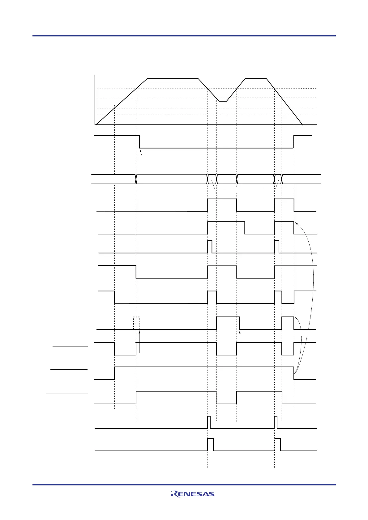
Figure 21-6. Timing of Voltage Detector Reset Signal and Interrupt Signal Generation
(Option Byte LVIMDS1, LVIMDS0 = 1, 0)
INTLVI
VLVIL
VLVIH
V
POR
= 1.51 V (TYP.)
V
PDR
= 1.50 V (TYP.)
LVIIF flag
Normal
operation
Normal
operation
Save processing
RESET RESET RESETOperation status
Internal reset signal
Supply voltage (V
DD)
LVIMK flag
(set by software)
Time
Cleared
LVD reset signal
Cleared by
software
Cleared by
software
Cleared by
software
POR reset signal
Note 2
Note 1
LVIOMSK flag
LVIRF flag
LVIMD flag
LVILV flag
LVIF flag
Cleared
LVISEN flag
(set by software)
(Notes and Remark are listed on the next page.)
<R>

 Loading...


