RL78/G13 CHAPTER 2 PIN FUNCTIONS
R01UH0146EJ0100 Rev.1.00 75
Sep 22, 2011
(2/6)
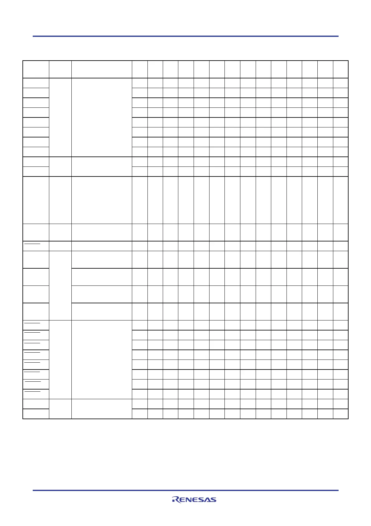
Function
Name
I/O Function
128-
pin
100
-pin
80-
pin
64-
pin
52-
pin
48-
pin
44-
pin
40-
pin
36-
pin
32-
pin
30-
pin
25-
pin
24-
pin
20-
pin
KR0
√ √ √ √ √ √ √ √ − − − − − −
KR1
√ √ √ √ √ √ √ √ − − − − − −
KR2
√ √ √ √ √ √ √ √ − − − − − −
KR3
√ √ √ √ √ √ √ √ − − − − − −
KR4
√ √ √ √ √ √ − − − − − − − −
KR5
√ √ √ √ √ √ − − − − − − − −
KR6
√ √ √ √ √ − − − − − − − − −
KR7
Input Key interrupt input
√ √ √ √ √ − − − − − − − − −
PCLBUZ0
√ √ √ √ √ √ √ √ √ √ √ √ √ −
PCLBUZ1
Output
Clock output/buzzer
output
√ √ √ √ √ √ √ √ √ √ √ − − −
REGC
−
Connecting regulator
output stabilization
capacitance for internal
operation.
Connect to V
SS via a
capacitor (0.47 to 1
μ
F).
√ √ √ √ √ √ √ √ √ √ √ √ √ √
RTC1HZ Output
Real-time clock correction
clock (1 Hz) output
√ √ √ √ √ √ √ √ − − − − − −
RESET Input System reset input
√ √ √ √ √ √ √ √ √ √ √ √ √ √
RxD0
Serial data input to
UART0
√ √ √ √ √ √ √ √ √ √ √ √ √ √
RxD1
Serial data input to
UART1
√ √ √ √ √ √ √ √ √ √ √ √ √ √
RxD2
Serial data input to
UART2
√ √ √ √ √ √ √ √ √ √ √ − − −
RxD3
Input
Serial data input to
UART3
√ √ √ − − − − − − − − − − −
SCK00
√ √ √ √ √ √ √ √ √ √ √ √ √ √
SCK01
√ √ √ √ √ √ − − − − − − − −
SCK10
√ √ √ √ − − − − − − − − − −
SCK11
√ √ √ √ √ √ √ √ √ √ √ √ √ √
SCK20
√ √ √ √ √ √ √ √ √ √ √ − − −
SCK21
√ √ √ √ √ √ √ √ √ − − − − −
SCK30
√ √ √ − − − − − − − − − − −
SCK31
I/O
Clock input/output for
CSI00, CSI01, CSI10,
CSI11, CSI20, CSI21,
CSI30, and CSI31
√ √ √ − − − − − − − − − − −
SCLA0
√ √ √ √ √ √ √ √ √ √ √ √ √ −
SCLA1
I/O
Clock input/output for
IICA0, IICA1
√ √ √ − − − − − − − − − − −
<R>

 Loading...


