- 7 -
4. Setting Up
4.1 Unpacking
Remove the device and all the accessories from the delivery package.
<RXZLOO¿QGPRUHDFFHVVRULHVLQWKHGXVWGUDZHU7RRSHQWKHGXVWGUDZHUVHHVHFWLRQ
Check the delivery for completeness (refer to the “3.3 Scope of Delivery” section).
4.2 Setup
7KHH[WUDFWLRQXQLWLVDIUHHVWDQGLQJDSSOLDQFHLQWHQGHGWREHVHWXSRQWKHÀRRUHJXQGHUWKHZRUN-
bench).
Up to four suction points can be connected to the extraction unit.
3RVLWLRQWKHH[WUDFWLRQGHYLFHVRWKDW
The exhaust air duct at the back of the unit is not hindered.
The distance to the suction points is approximately even (see section 4.5).
The front of the device is easily accessible for removal of dust drawer.
4.2.1 Integration in existing Workbench
If the extractor is to be integrated within an existing workbench, it is essential to ensure of an
external source of cooling air! Please use the cool air tube which is available as an accessory.
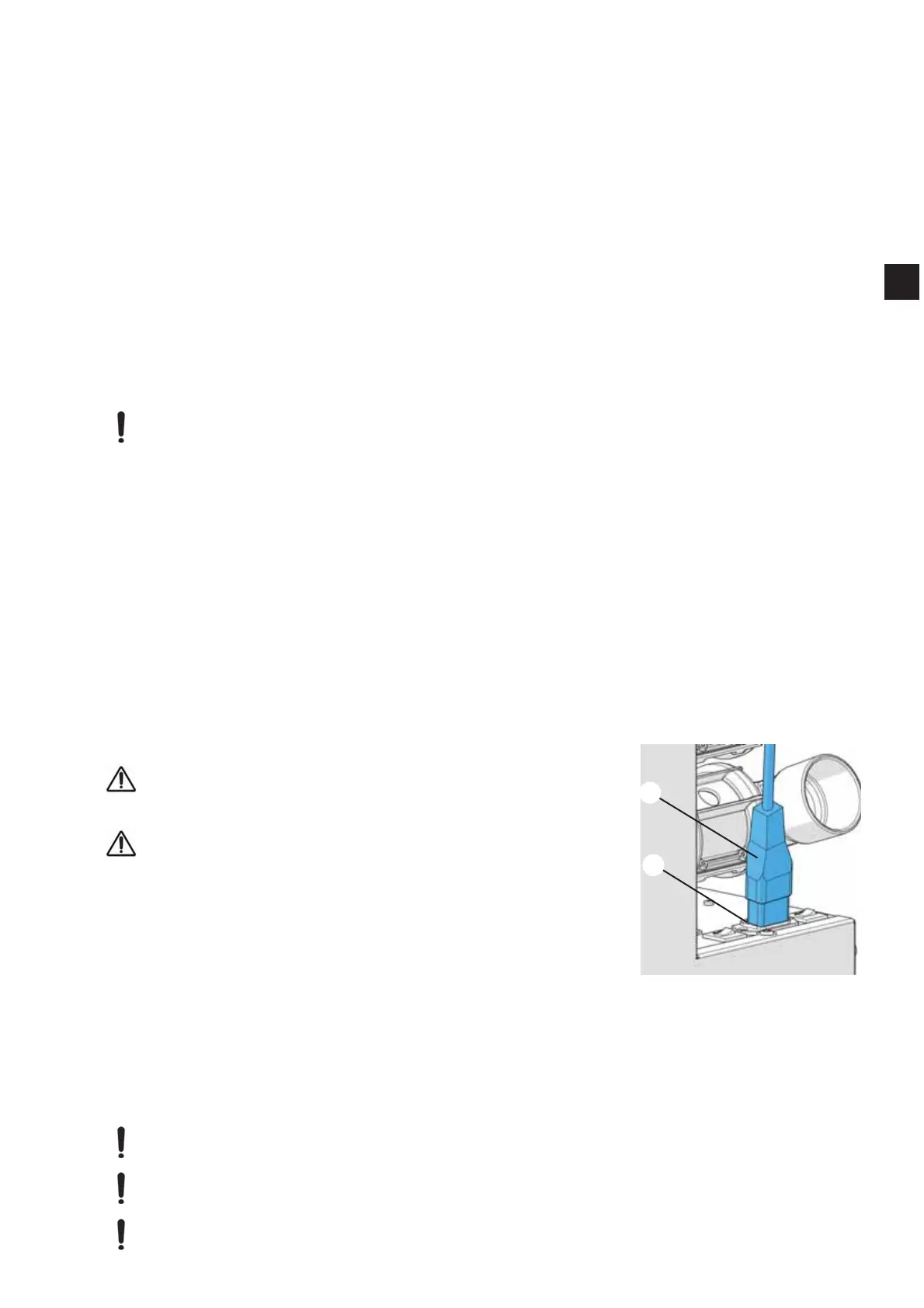
Insert the cool air tube into the cool air connection (19, Fig.1).
3RVLWLRQWKHFRRODLUWXEHVRWKDW
- Cool air is sucked in and not the warmed air exhaust air from the extraction unit.
- 1RGLUWLVVXFNHGLQHJGRQRWSODFHRQWKHÀRRU
A ventilation outlet is necessary to allow the warm exhaust air coming from the back of the device to
HVFDSH7KHDLUYHQWLODWLRQSDVVDJHZD\PXVWEHDWOHDVWFPðLQVL]H,WLVSRVVLEOHWRXVHWKHH[WHU-
nal exhaust air duct (see accessories).
The height of the unit can be altered via the adjustable feet at the base of the unit (see accessories).
The installation details are supplied with the unit feet.
4.2.2 External Exhaust Air Route
An external exhaust air route (see accessories) allows the extracted air to leave the laboratory.
The installation details are supplied with the external exhaust air route.
4.3 Electrical Connection
Before connecting the device, ensure that the voltage infor-
PDWLRQRQWKHLGHQWL¿FDWLRQSODWHFRUUHVSRQGVZLWK\RXUORFDO
power supply.
Arrange the conducting parts (plug sockets, plugs and cou-
plings) and install the extension cord so that the protection
class is retained.
Switch the device OFF at the On / Off switch (3, Fig.1)
Connect the power cable (18) to the power supply (13). With
WKH9YHUVLRQWKHSRZHUFDEOHLV¿UPO\DWWDFKHGWRWKH
extraction unit.
Insert the mains cable into the plug socket.
4.4 Compressed Air Connection
7KHH[WUDFWLRQXQLWUHTXLUHVFRPSUHVVHGDLUIRUWKHIROORZLQJUHDVRQV
To open and close the pneumatic pinch valves,
)RUWKHDXWRPDWLF¿OWHUFOHDQLQJIXQFWLRQ
On the device, the compressed air tube is sealed (9, Fig. 1).
Connect the compressed air tube with assembled coupling to the compressed air supply.
Observe the minimum / maximum connection pressure; see section 8.1, Technical Data!
'RQRWFKDQJHWKHFRXSOLQJ¿WWLQJRQWKHFRPSUHVVHGDLUWXEHIRUDVPDOOHUYHUVLRQ
The compressed air must be clean, dry (no condensation) and free from oil. Moist compressed
air can cause damage to the appliance!
The compressed air supply tube leading from the compressor to the appliance should be no
less than 10 mm in diameter.
Fig.
18
13
EN