50
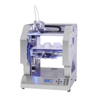
Installation of the main PCB
1x main PCB
5x spacer roller 20 mm
5x cylinder head screw M3x25
5x nut M3
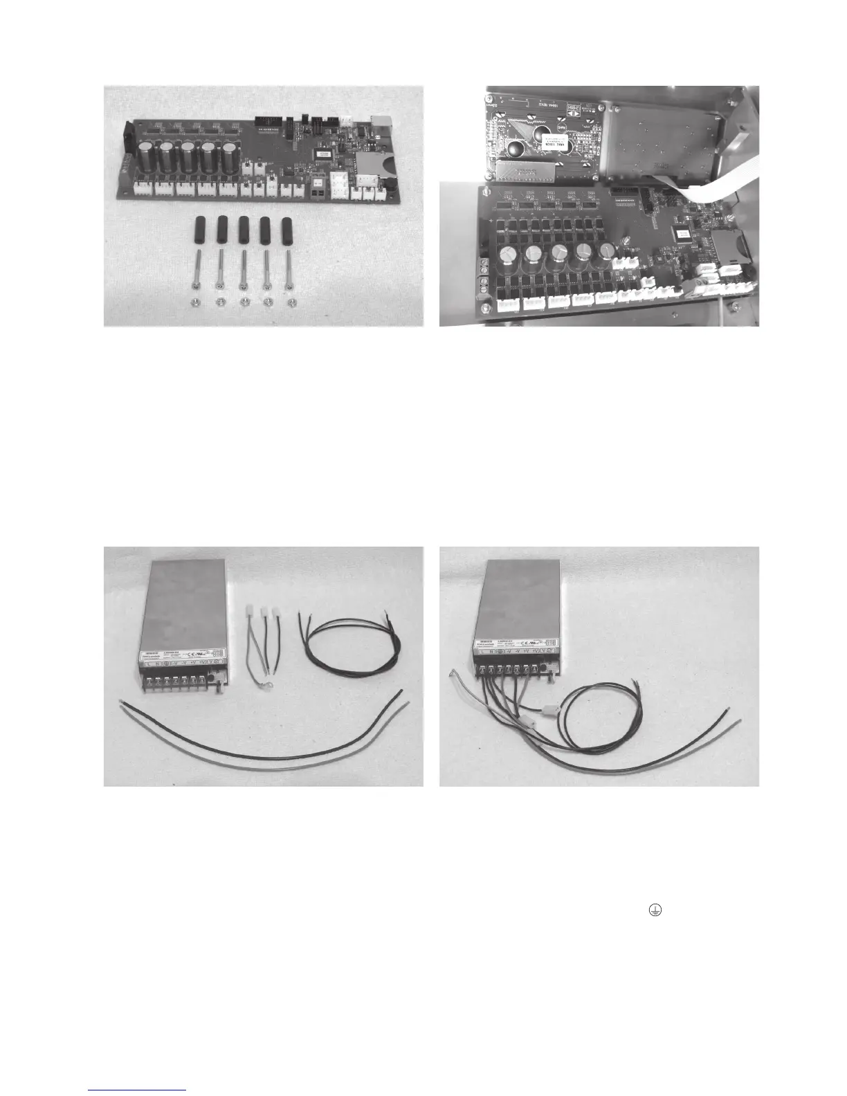
Install the main PCB with the spacer rollers 20 mm as shown.
The spacer rollers may be fastened to the PCB with a drop of
hot glue for easier assembly first.
Apply all screws in the area of the nuts with threadlocker var-
nish.
Align the PCB so that the USB connection and the memory
card reader are placed cleanly behind the respective housing
cut-outs.
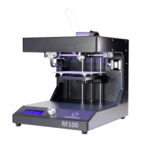
Connection of the lines at the mains unit
1x mains unit
1x line with flat plug connector black (short)
1x line with flat plug connector blue (short)
1x line with flat plug connector green/yellow (short)
1x line black (61 cm)
1x line blue (61 cm)
1x line red (37 cm)
1x line black (37 cm)
Remove the transparent protective cover at the clamping strip
of the mains unit.
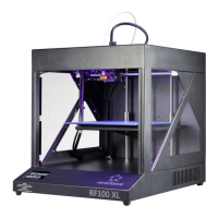
Connect the line with flat plug connector black (short) and line
black (61 cm) to the terminal L at the mains unit.
Connect the line with flat plug connector blue (short) and line
blue (61 cm) to the terminal N at the mains unit.
Connect the line with the flat plug connector green/yellow
(short) to the protective ground terminal at the mains unit.
Connect the line red (37 cm) to the terminal +V at the mains
unit.
Connect the line black (37 cm) to the terminal -V at the mains
unit.
Put on the transparent protective cover at the clamping strip of
the mains unit again.