51
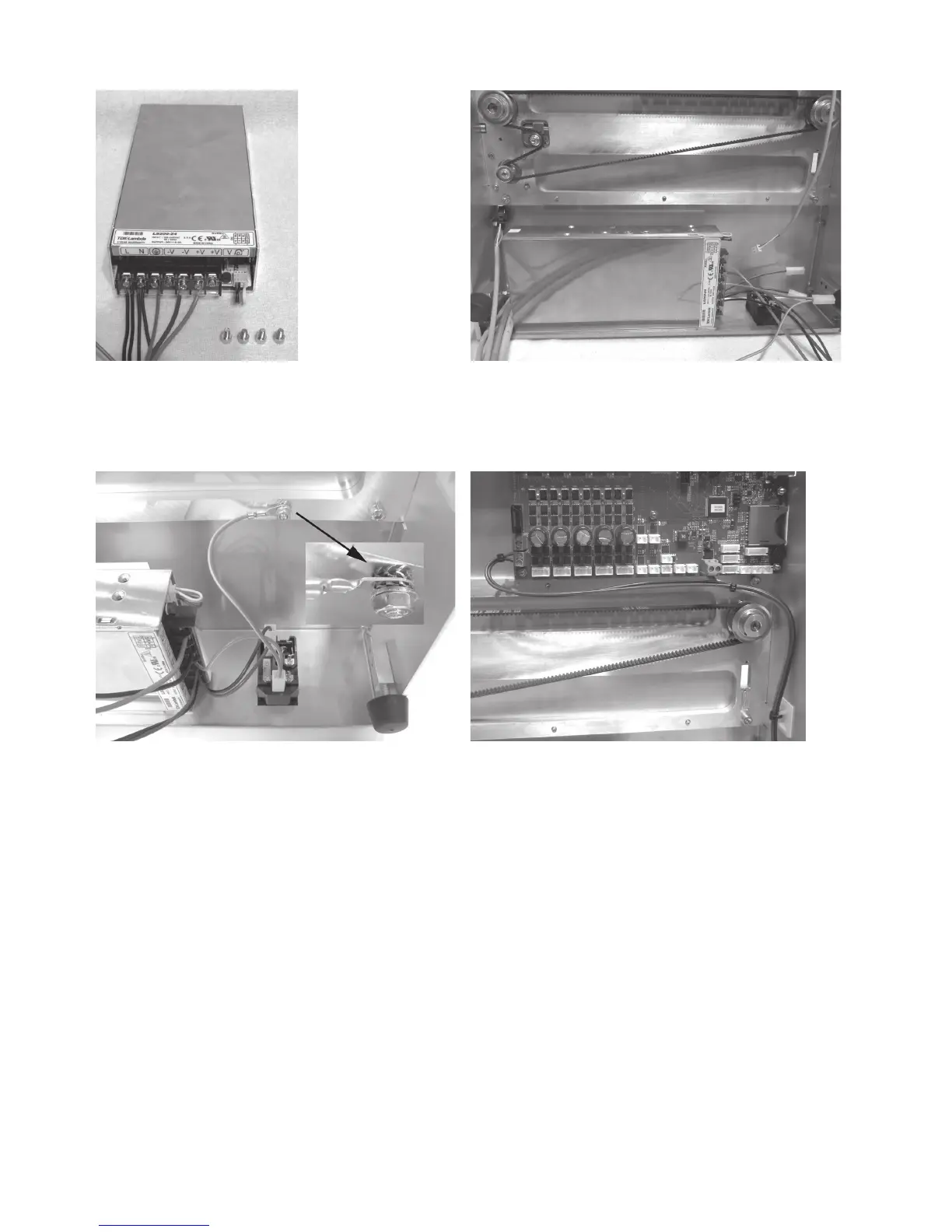
Installation of the mains unit
1x mains unit with already-connected lines
4x cylinder head screw M4x6
Attach mains unit with the 4 screws at the rear cover.
Connection of the mains unit
Plug the line with flat-plug connector black (short) to the up
-
per switching contact tab of the low power device combination
socket.
Plug the line with flat-plug connector blue (short) to the contact
of the low power device combination socket tab below it.
Plug the line with flat-plug connector green/yellow (short) to
the protective ground contact tab of the low power device
combination socket tab.
Connect the ring eyelet of the green/yellow line as indicated to
the long attachment screw of the rear cover.
Caution: This connection creates the safety-technically im-
portant contact between the housing parts and the protec-
tive ground. Always observe the position of the washers and
sprockets:
Housing > sprocket > ring eyelet > sprocket > washer > nut M4
(see image section)
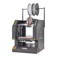
Connect the line black (61 cm) and line blue (61 cm) to the ter-
minals X28 of the main PCB.
Connect the line red (37 cm) and line black (37 cm) to the termi-
nals X1 of the main PCB.
Attention, observe polarity of the lines:
red = + (left terminal in the figure)
black = - (right terminal in the figure)
Route the lines cleanly with cable ties and a self-adhesive ca-
ble tie holder and secure them.
The lines must not get into the rotating toothed belts in opera-
tion.