53
Connection of the device lines
Connect the device lines to the main PCB as follows:
Line Terminal main PCB Connected components
8 X15 Limit switch Z-direction
9 X26 LED lighting right
10 X27 LED lighting left
11 X13 Limit switch X direction
12 X9 Thermal sensor heating plate
13 X14 Limit switch Y-direction
14 X5 Thermal sensor extruder
15 X7 Elongation measuring strip
16 X16 Motor Z-direction
17 X11 Motor X-direction
18 X12 Motor Y-direction
19 (4-pin) X17 Motor extruder
19 (2-pin red/blue) X24 Fan
19 (2-pin pink/grey) X4 Heating extruder
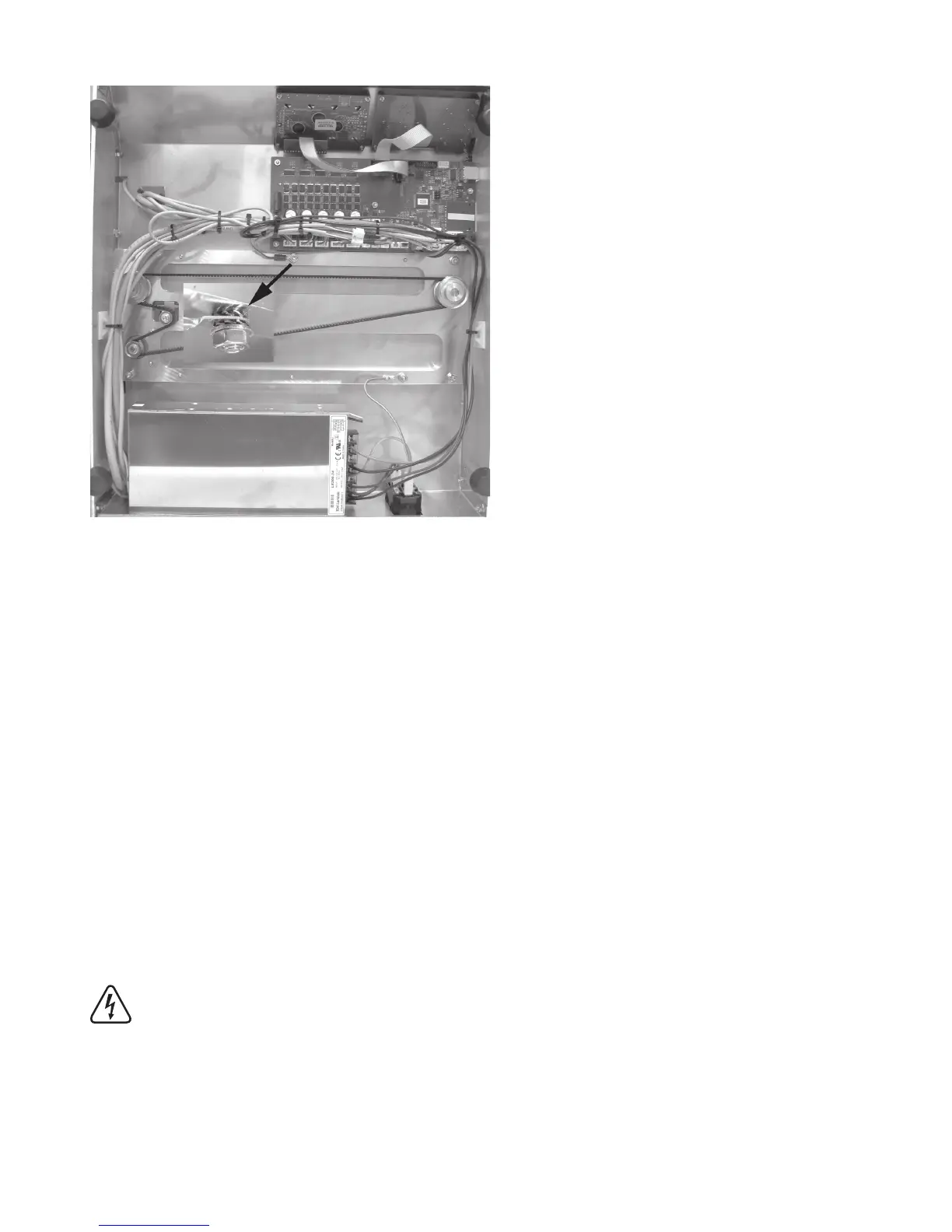
20 X29 + protective ground at middle screw operating unit cover Heating plate
The ring eyelet of the protective ground at line 20 is attached with sprockets and an additional nut at the middle attach-
ment screw of the operating unit cover.
Caution: This connection creates the safety-technically important contact between the housing parts and the protec
-
tive ground. Always observe the position of the washers and sprockets:
Housing > sprocket > ring eyelet > sprocket > washer > nut M4 (see image section)
Route the lines cleanly with small cable ties (99 mm) and a self-adhesive cable tie holder and secure them.
The lines must not get into the rotating toothed belts in operation.