15
Typical Setup
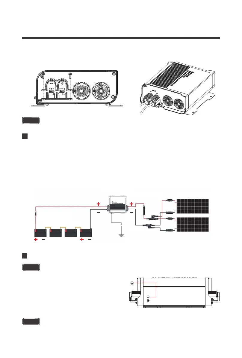
200W System, 48V System
A typical setup is demonstrated utilizing 2 x 100W panels in parallel where all the positive
connectors connect, and all the negative connections connect before they are connected at
the input of the Rover Boost. Other items include: a set of MC4 branch connectors, an inline
MC4 fuse, an Adapter kit, the 10A Rover Boost, a set of tray cables, an ANL Fuse set and
cable, battery interconnects, and a 48V battery bank system.
NOTE
The M3 screws have a recommended torque of 0.5~0.8 N-m / 0.4~0.6 lbf. ft.
NOTE
The M3 screws have a recommended torque of 0.5~0.8 N-m / 0.4~0.6 lbf. ft.
When finished, place the removable PV input cable housing back over your connections.
Make sure to not over-tighten the M3 screws.
3.
CAUTION
Grounding
Do NOT ground PV input and Battery output individually, use the controller ground lug.
Grounding is not necessary for the operation and
is at user’s discretion. If grounding, do not ground
the PV input and Battery output connections
together. Instead, Locate the M3 ground screw
on the front of the Rover Boost. Unscrew the
terminal, place a M3 ring connector and ground
the system to earth ground.
10A Rover Boost
Solar Panels(Parallet)
10-12A MC4 Fuse
12-10AWG Tray Cable
15A
ANL Fuse Set+Cable
48V Battery System
Battery Interconnects
Ground
MC4 Branch
Connectors
12-10AWG
Adapter Kit