16
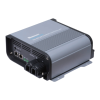
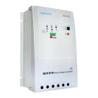
Connecting the Temperature Sensor (Model: RTSCC)
The RTSCC will include the 2-pin green housing connector. Simply connect the 2-pin
connector to the TEMP port on the OUTPUT side of the Rover Boost.
NOTE
Separate purchase required.
SET
TYPE
rs485 can
BATT
temp batt
PV
output
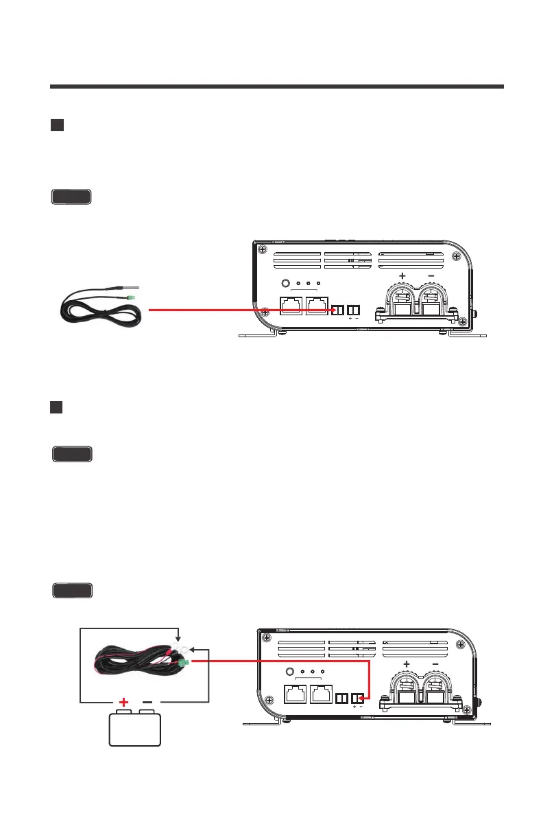
Connecting the Battery Voltage Sensor (Model: RVSCC)
The RVSCC is polarity sensitive and you must connect it to the correct positive (+,
left pin) and the correct negative (-, right pin) battery terminals as well as match the
polarity written on the BATT port on the Rover Boost (+, -).
The RVSCC will include the 2-pin green housing connector on one end as well as
positive and negative ring connectors on the other end. First connect the negative
and positive ring terminals to your battery bank. Make sure it is the correct polarity.
Next, simply connect the 2-pin connector to the BATT port on the OUTPUT side of
the Rover Boost.
NOTE
Separate purchase required.
SET
TYPE
rs485 can
BATT
temp batt
PV
output
CAUTION