05
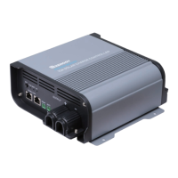
Left View
5.RS485 / CAN Communication Ports
6.Setting Button
(Battery Type,CAN Host Mode)
7.Battery Type LED Indicator
8.Battery Status LED Indicator
9.PV Status LED Indicator
10.36/48V Positive Battery Output Terminal
11.36/48V Negative Battery Output Terminal
12.Removable Battery Output Cable Housing
13.Battery Voltage Sensor Port
(Polarity Sensitive, Optional)
14.Battery Temperature Sensor Port (Optional)
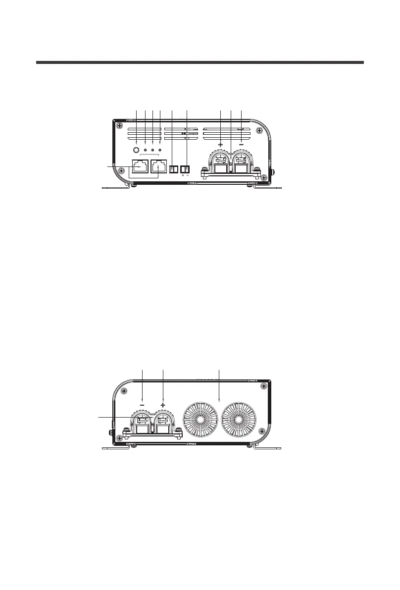
15. Removable PV Input Cable Housing
16. Negative PV Input Terminal
17. Positive PV Input Terminal
18. Cooling Fans
Right View
input
SET
TYPE
rs485 can
BATT
temp batt
PV
output
76
5
8 9 14 13 10
16 17
15
18
12 11