Prusa i3 – Build Manual
4.2 Ramps Y & Z Wiring
Now is a good time to deal with the wiring for the Y and Z axis. Firstly secure the wiring out of the way of the
build plate by cable tieing onto the M10 and M8 threaded rods (Fig 4.2b). Then connect the Z-axis motors to
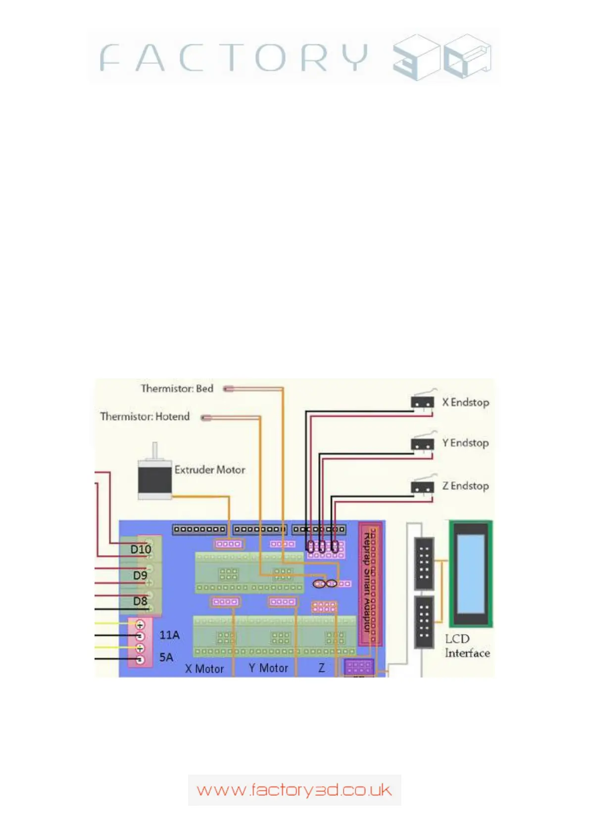
the top right twin 4pin connectors and the Y-axis motor to the middle right 4pin connector (red wire up).
Finally Connect the Z-endstop and Y-endstop wires to the left two pins of the 18 pin bank of pins at the top left.
The 18 pin bank of pins is in 6 rows of 3, if the bottom row is row 1 and the top row is row 6, connect the Y-
axis to row 3 and the Z-axis to row 5 (X-axis goes on row 1), see Fig 4.2c. (Note: An older style ramps mount
is shown here with 2 pin endstop connectors, this makes no difference the connection is still on the left two pins
of the bank even if you have 3 pin connectors, normally the 3
rd
pin will have been disabled)
Note: If you connect your endstops to the incorrect pins you will destroy your electronics the moment an
endstop is triggered (you will be able to smell your Mega 2560 burning). It will save time and money re-
reading and triple checking your endstop connections before powering up, take as long as necessary until
your 100% sure your connected correctly. Looking at the RAMPS from the rear of the machine , the 18
pin bank, 6 rows of 3 pins. Your endstops connect to the left hand two pins (see 4.2a and 4.2c showing the
connectors attached to the left two pins). If your end-stop connector housings are 3 pin, the third pin will
be disabled. See also the RAMPS wiring diagram in section 8, as well as the RAMPS 1.4 wiki online.
Fig 4.2a
Version: 1.3 Page: 20