Form CP-MAPSIII-D21, Doc No 303070, Page 28
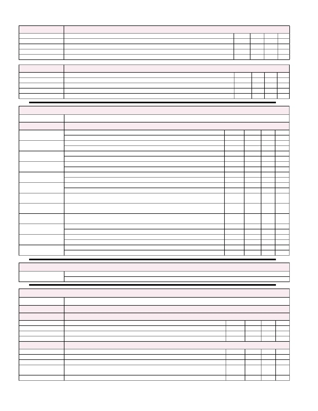
Schedule B6 Schedule Screen B6 will be displayed if unit OccMode_Sel is set to Schedule
Name Description Default Unit Min Max
9: Sets the desired Holiday Range 9: For Extended Unoccupied Mode 0/0 - 0/0
10: Sets the desired Holiday Range 10: For Extended Unoccupied Mode 0/0 - 0/0
11: Sets the desired Holiday Range 11: For Extended Unoccupied Mode 0/0 - 0/0
12: Sets the desired Holiday Range 12: For Extended Unoccupied Mode 0/0 - 0/0
Schedule B7 Schedule Screen B7 will be displayed if unit OccMode_Sel is set to Schedule
Name Description Default Unit Min Max
13: Sets the desired Holiday Range 13: For Extended Unoccupied Mode 0/0 - 0/0
14: Sets the desired Holiday Range 14: For Extended Unoccupied Mode 0/0 - 0/0
15: Sets the desired Holiday Range 15: For Extended Unoccupied Mode 0/0 - 0/0
16: Sets the desired Holiday Range 16: For Extended Unoccupied Mode 0/0 - 0/0
Main Menu
C Points List Points List Menu - Applicable screens and content will be displayed depending upon unit conguration
See Hardware Point Table on page 4 for Complete List of IO Points and Serial Communication Connections
Points List C1
Points List Screen C1
ApplicableAnalogOutputsforUnitConguration
Points List C2
Points List Screen C2
ApplicableRelayOutputsforUnitConguration
Points List C3
Points List Screen C3
ApplicableRelayOutputsforUnitConguration
Points List C4
Points List Screen C4
ApplicableRelayOutputsforUnitConguration
Points List C5
Points List Screen C5
ApplicableAnalogInputsforUnitConguration
Points List C6
Points List Screen C6
ApplicableAnalogInputsforUnitConguration
Point Lists C7 thru
C12
Points List Screens C7 thru C12 contain the temp & humidity values for the
optional space sensors 1 thru 6.
Points List C13
Point List Screen C13 contains the temp & humidity values for the optional
return air temp probe
Points List C14
Point List Screen C14 contains the temp & humidity values for the optional
exhaust air temp probe
Points List C15
Points List Screen C15
ApplicableDigitalInputsforUnitConguration
Points List C16
Points List Screen C16
ApplicableDigitalInputsforUnitConguration
Points List C17
Points List Screen C17
ApplicableDigitalInputsforUnitConguration
Main Menu
D Alarms
Alarms Menu - Active Alarms are displayed with the option of entering the Alarm Logger
See Alarm Management Section paragraph 4.2 of this document for detailed information on Active and Logged alarms
Main Menu
E Service Service Menu
a Test Mode Test Mode Menu
Test Mode Ea1 Test Mode Screen Ea1
Name Description Default Unit Min Max
Enable: ModiableFieldUsedtoenabletheTestMode
Time Out: ModiableFieldUsedtoadjustthetestmodetimeduration 120 min 0 240
Countdown: Current status of the time remaining for Test Mode if active min / s
Test Mode Ea2 Test Mode Screen Ea2
Name Description Default Unit Min Max
Damper: Automatically Commanded Percentage Output to unit Damper(s) 100 % 100 100
Supply: Automatically Commanded Supply Fan Start Output
Supply:
SupplyFanSpeedOutputModiableFieldusedtotestunitSupplyFanVFDandset
Air Balance fan speed adjustment
100 % 30 100
Airow Status: Status of Supply Fan Air Proving Switch Off On
7.0 Controller Display Menus (cont’d)