Form CP-MAPSIII-D21, Doc No 303070, Page 29
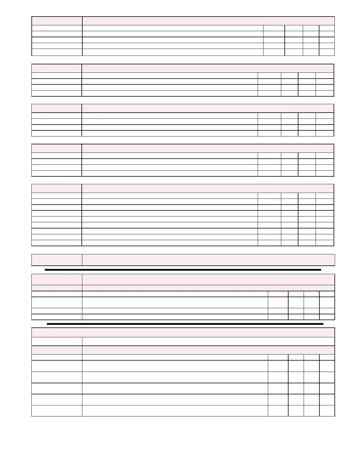
Test Mode Ea3 Test Mode Screen Ea3
Name Description Default Unit Min Max
Stage 1: ModiableFieldusedtoturnonCompressorStage1 Off Off On
Stage 2: ModiableFieldusedtoturnonCompressorStage2 Off Off On
Stage 3: ModiableFieldusedtoturnonCompressorStage3 Off Off On
Stage 4: ModiableFieldusedtoturnonCompressorStage4 Off Off On
Test Mode Ea4 Test Mode Screen Ea4 will be displayed if unit is congured with a Reheat Compressor
Name Description Default Unit Min Max
Reheat Comp: ModiableFieldusedtoturnonReheatCompressor Off Off On
Reheat Capacity: ModiableFieldusedtosetpercentagecommandtoReheatValve 0 % 0 100
Output: Output in vdc to Reheat Valve 0 vdc 0 10
Test Mode Ea5 Test Mode Screen Ea5
Name Description Default Unit Min Max
Stg 1: ModiableFieldusedtoturnonHeatingStage1 Off Off On
HX1 Capacity: ModiableFieldusedtosetpercentagecommandtoHX1modulationvalve 0 % 0 100
Output: Output in vdc to HX1 modulation Valve 0 vdc 2 10
Test Mode Ea6 Test Mode Screen Ea6 will be displayed if unit is congured with two Heat Engines
Name Description Default Unit Min Max
Stg 2: ModiableFieldusedtoturnonHeatingStage2 Off Off On
HX2 Capacity: ModiableFieldusedtosetpercentagecommandtoHX2modulationvalve 0 % 0 100
Output: Output in vdc to HX2 modulation Valve 0 vdc 2 10
Test Mode Ea7 Test Mode Screen Ea7
Name Description Default Unit Min Max
Heat Capacity: ModiableFieldusedtoadjusttheoutputtotheSCRController 0 % 0 100
Output: Output in vdc to modulated heating component: Electric = SCR 0-10; 0 vdc 0 10
Stg 1: ModiableFieldusedtoturnonHeatingStage1 Off Off On
Stg 2: ModiableFieldusedtoturnonHeatingStage2 Off Off On
Stg 3: ModiableFieldusedtoturnonHeatingStage3 Off Off On
Stg 4: ModiableFieldusedtoturnonHeatingStage4 Off Off On
Stg 5: ModiableFieldusedtoturnonHeatingStage5 Off Off On
Stg 6: ModiableFieldusedtoturnonHeatingStage6 Off Off On
Test Mode Screens
Ea8 thru Ea20
Test Mode Screens Ea8 through Ea20 contain all applicable analog and binary hardware sensor inputs, including
any serial communicated sensors depending upon unit conguration.
b TAB
TAB Menu - Used to perform a Service Save of controller setpoints and to perform a Service Restore of
previously saved setpoints
TAB Eb1 TAB Screen Eb1
Name Description Default Unit Min Max
Set Max SF Spd?
ModiableFieldusedtosettheoptionalSFSpdClgSP and SFSpdHtgSP to the
SFSpdMax_SPforsaving(thiseldwillbeshownifVFDoptions1,2or3areselected)
No No Yes
Save? ModiableFieldusedtoperformaServiceSaveofcurrentsetpoints No No Yes
Restore? ModiableFieldusedtoperformaServiceRestoreofcurrentsetpoints No No Yes
Main Menu
c Supply Fan Supply Fan Menu - Applicable screens and content will be displayed depending upon unit conguration
Supply Fan Ec1 Supply Fan Screen Ec1
Name Description Default Unit Min Max
Control:
Selected Fan Control Strategy - Constant Vol, Bldg Pressure, Duct Pressure, 0-10vdc
input or BMS source
SFSpdClgSP:
Supply Fan Speed Cooling SP - Sets commanded speed for the supply fan when in
cooling mode
100 % 30 100
SFSpdHtgSP:
Supply Fan Speed Heating SP - Sets commanded speed for the supply fan when in
heating mode
100 % 30 100
SFSpdLoSP:
Supply Fan Speed Low SP - Sets commanded speed for the supply fan when the unit is
not in either the heating or the cooling mode.
100 % 30 100
SFSpdHiSP:
Supply Fan Speed High SP - Sets commanded speed for the supply fan when the unit is
in either the heating or the cooling mode.
100 % 30 100