Form CP-MAPSIII-D21, Doc No 303070, Page 30
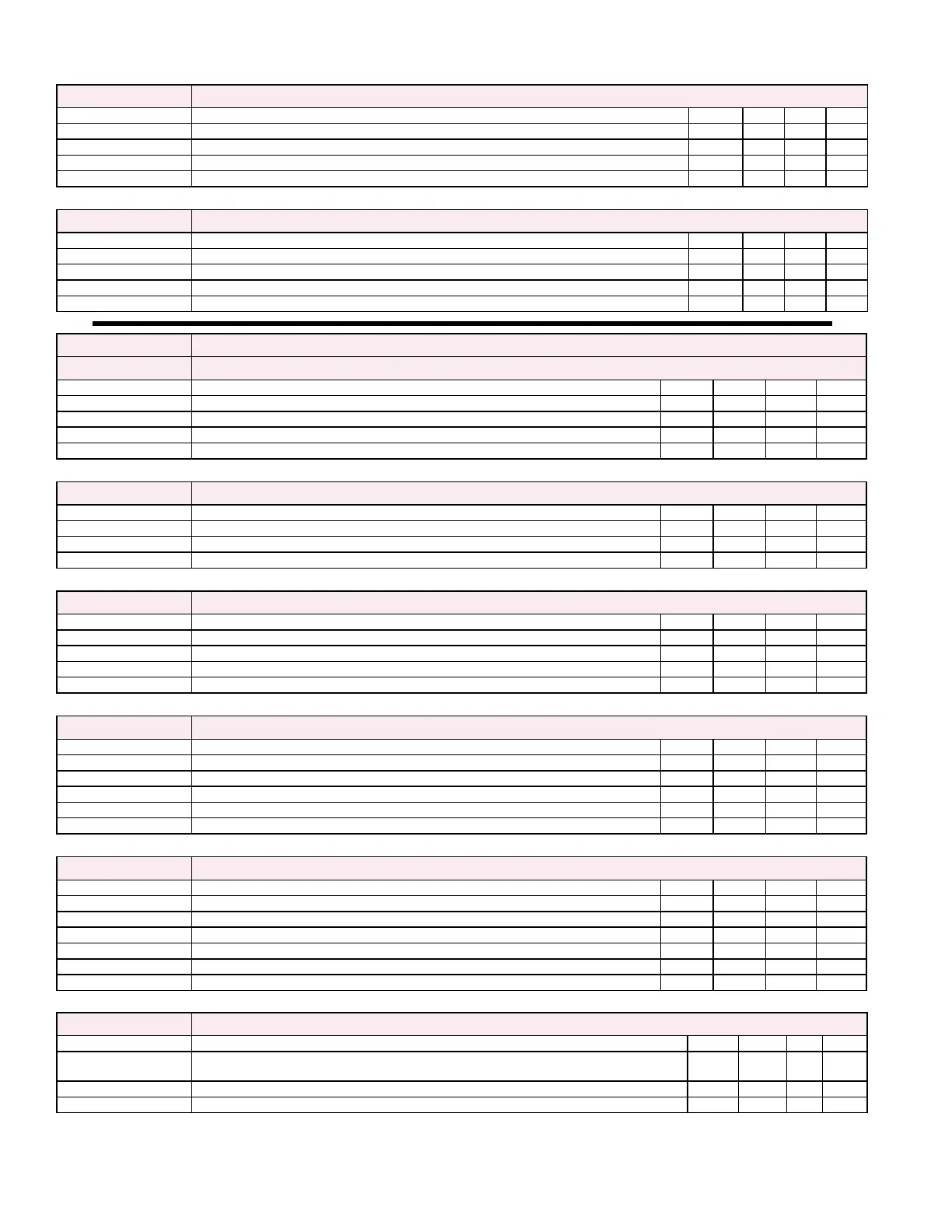
Supply Fan Ec2 Supply Fan Screen Ec2 will be displayed if Supply Fan is selected for Bldg Pressure Control
Name Description - Supply Fan Bldg Pressure Control Loop Monitoring Default Unit Min Max
Bldg Pressure Current Building Static Pressure iwc -0.5 0.5
Setpoint: Current Building Static Pressure SP 0.1 iwc -0.5 0.5
PI Output: Current output of the control loop % 0 100
SF_VFD_Cmd Current Supply Fan VFD Command in vdc vdc 0 10
Supply Fan Ec3 Supply Fan Screen Ec3 will be displayed if Supply Fan is selected for Duct Pressure Control
Name Description - Supply Fan Duct Pressure Control Loop Monitoring Default Unit Min Max
Duct Pressure Current Duct Static Pressure iwc 0 2.5
Setpoint: Current Duct Static Pressure SP 0.5 iwc 0 2.5
PI Output: Current output of the control loop % 0 100
SF_VFD_Cmd Current Supply Fan VFD Command in vdc vdc 0 10
d Capacity Capacity Menu - Applicable screens and content will be displayed depending upon unit conguration
Capacity Ed1 Capacity Screen Ed1 (Monitor Only)
Name Description Default Unit Min Max
Heat Type: Selected Heating Type Gas or Electric
Heating Stages: Number of Heating Stages
Cooling Stages: Number of Cooling Stages
Reheat: Unit Reheat Selection - Enable or Disabled
Capacity Ed2 Capacity Screen Ed2
Name Description Default Unit Min Max
th- Space Sens: th- Space Sens - Enables and disables option CL78 space sensor 1 Off
Spc_Avg_Ena: Spc_Avg_Ena - Enables averaging of multiple space sensors from 2 up to 6. Off
Num_Avg_Sens: Num_Avg_Sens - Sets the number of sensors to average including the th-Tune 2 2 6
Capacity Ed3 Capacity Screen Ed3
Name Description Default Unit Min Max
OAHtgLo_SP OA Heating Lockout SP - Sets OA setpoint used to disable heating 65 Deg F 0 150
OAHtgLoDiff OA Heating Lockout SP Differential - Sets differential used for the OAHtgLo_SP 2 Deg F 05 10
OAClgLo_SP OA Cooling Lockout SP - Sets OA setpoint used to disable mechanical cooling 65 Deg F -10 150
OAClgLoDiff OA Cooling Lockout SP Differential - Sets differential used for the OAClgLo_SP 2 Deg F 05 10
Capacity Ed4 Capacity Screen Ed4 will be displayed if the unit is congured with Heating
Name Description - Heating Demand Control Loop Monitoring Default Unit Min Max
DA_Temp Current Discharge Air Temp Deg F
Setpoint: Current Discharge Air SP Deg F
PI Output: Current output of the control loop % 0 100
HX1_Mod_Cmd Heating Modulation 1 Command in vdc vdc 0-2 10
HX2_Mod_Cmd Heating Modulation 2 Command in vdc vdc 0-2 10
Capacity Ed5 Capacity Screen Ed5 will be displayed if the unit is congured with Heating
Name Description - Heating Stages Default Unit Min Max
HX_Stg1_Cmd Current Heating Stage 1 Command Off On
HX_Stg2_Cmd Current Heating Stage 2 Command Off On
HX_Stg3_Cmd Current Heating Stage 3 Command Off On
HX_Stg4_Cmd Current Heating Stage 4 Command Off On
HX_Stg5_Cmd Current Heating Stage 5 Command Off On
HX_Stg6_Cmd Current Heating Stage 6 Command Off On
Capacity Ed6 Capacity Screen Ed6
Name Description - Cooling Demand Control Loop Monitoring Default Unit Min Max
Active Input:
Currentcontrollinginputforcooling-DA_Tempor(CC_TempusedinDehumidication
Mode)
Deg F
Setpoint: CurrentDischargeSPor(CoolingCoilSPusedinDehumidicationMode) Deg F
PI Output: Current output of the control loop % 0 100
7.0 Controller Display Menus (cont’d)