10
NSA-002A User Manual A00
2.3 Ports / Pinouts
In this chapter all Ports / Pinouts of the NSA-002A are shown.
Analog IN & Analog OUT Port
The analog inputs and outputs have following pinouts.
female = inputs
male = outputs
figure 3: Analog in/out port XLR-3 pinout
·
Nom. input/output level: +6 dBu
·
Max. input/output level: +24 dBu
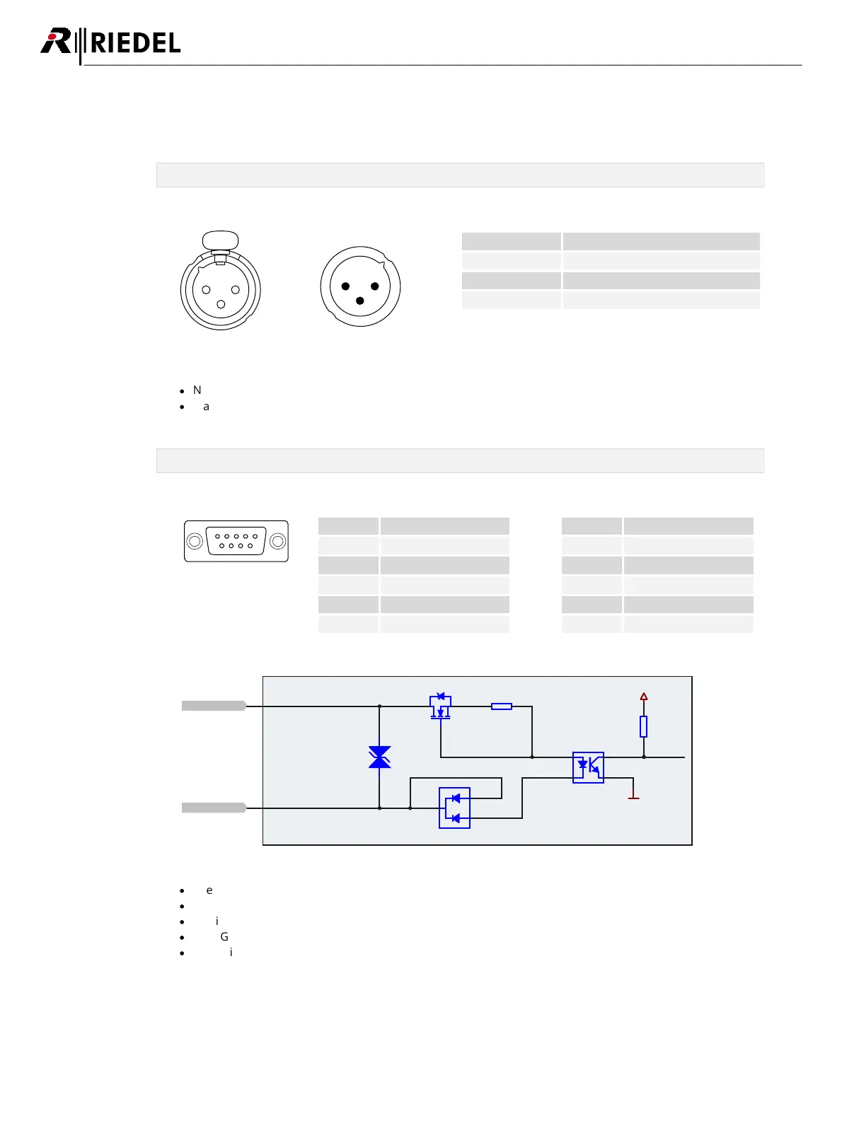
GPI port
The GPI input connector contains 3 single ports.
Figure 4: GPI IN connector Sub-D-9 female pinout
Figure 5: GPI IN connector schematic
·
The input voltage range of the GPI inputs is +5 to +30 VDC (~5 mA current draw, internal optocouplers).
·
The polarity of the inputs is important. The higher potential must be connected to “P” of each channel.
·
The inputs are galvanically isolated.
·
The "GPIO +5V" output voltage drops when increasing the: 5V @ 0mA / 3.3V @ 50mA.
·
The switching threshold is between 0.8 VDC and 2.0 VDC.