- 16 -
EXTERNAL PROTECTIVE DEVICES
LINE PROTECTION: MAGNETOTHERMAL OR FUSE
Within the CPS there are protection devices for output and internal faults.
You must protect the input line (and the separate bypass line if present) with the appropriate protection devices. These devices
must comply with the regulations of the country where the CPS is installed.
In order to set up the power line, install a magnetothermal switch upstream from the CPS with intervention curve C or D
(breaking capacity ≥6kA) or gR type fuse. Please follow the indications in the table below:
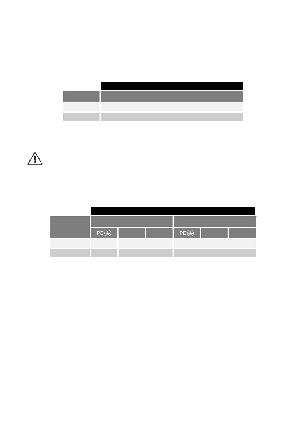
Automatic external protective devices
Model Mains single-phase input (1P+N)
3 kVA 20A (Max 40A)
5 kVA 32A (Max 40A)
SAFETY DEVICES: DIFFERENTIAL
The CPS can cause a D.C. current in the PE conductor.
An RCD located upstream is suggested: its trip current should be the sum of CPS + Load leakage current, with a
suitable margin to prevent unwanted interventions.
Only a RCD Type B is allowed.
CONNECTION CABLES CROSS SECTION DETAILS
To determine the minimum cross section of the input and output cables, see the table below:
Cross section of cables (sqmm)
*
Model
INPUT OUTPUT
N L
N L
3 kVA 10 4 (10 max) 4 (10 max)
5 kVA 10 6 (10 max) 6 (10 max)
*
The cross sections indicated in the table refer to a maximum length of 10 meters.
The cross sections refer to bare cables (without terminals).
Note: the length of the cable stripping must be equal to 15mm
 Loading...