20154249
16
Installation
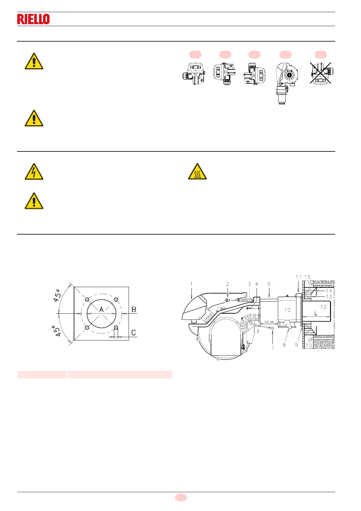
5.4 Operating position
5.5 Opening the burner
5.6 Preparing the boiler
5.6.1 Boring the boiler plate
Pierce the closing plate of the combustion chamber, as in Fig. 10.
The position of the threaded holes can be marked using the
thermal insulation screen supplied with the burner.
Tab. I
5.6.2 Blast tube length
The length of the blast tube must be selected according to the
indications provided by the manufacturer of the boiler, and in any
case it must be greater than the thickness of the boiler door
complete with its fettling.
The available length L (mm) is 372 mm.
For boilers with front flue passes 15)(Fig. 11), or flame inversion
chamber, a protection in refractory material 13)(Fig. 11) must be
inserted between the boiler fettling 14) and the blast tube
12)(Fig. 11).
This protection must not compromise the extraction of the blast
tube.
For boilers with water-cooled front piece, the refractory protection
13-14)(Fig. 11) is not necessary, unless specifically requested by
the boiler manufacturer.
The burner is designed to operate only in
positions 1, 2, 3 and 4 (Fig. 9).
Installation 1 is preferable, as it is the only
one that allows the maintenance operations
as described in this manual.
Installations 2, 3 and 4 allow operation but
make maintenance and inspection of the
combustion head more difficult.
Any other position could compromise the
correct operation of the appliance.
Installation 5 is forbidden for safety reasons.
Disconnect the electrical supply from the burner
by means of the system main switch.
Close the fuel shut-off valve.
Wait for the components in contact with heat
sources to cool down completely.
Model A B C
RS 190/M 230 325 - 368 M16
 Loading...