20154249
24
Start-up, calibration and operation of the burner
6.1 Notes on safety for the first start-up
6.2 Adjustments prior to ignition
Combustion head adjustment is already described on page 19.
In addition, the following adjustments must also be made:
open the manual valves upstream of the gas train.
Adjust the minimum gas pressure switch to the start of the
scale.
Adjust the maximum gas pressure switch to the end of the
scale.
Adjust the air pressure switch to the start of the scale.
Purge the air from the gas line.
We recommend using a plastic tube routed outside the
building and to purge air until gas is smelt.
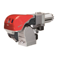
Fit a U-type pressure gauge or a differential pressure gauge
(Fig. 27), with socket (+) on the gas pressure of the pipe
coupling and (-) in the combustion chamber.
The manometer readings are used to calculate MAX burner
output using the Tab. J.
Connect two lamps or testers to the two gas line solenoid
valves to check the exact moment in which voltage is
supplied.
This operation is not required if each of the two solenoid
valves is equipped with a pilot light that signals voltage
passing through.
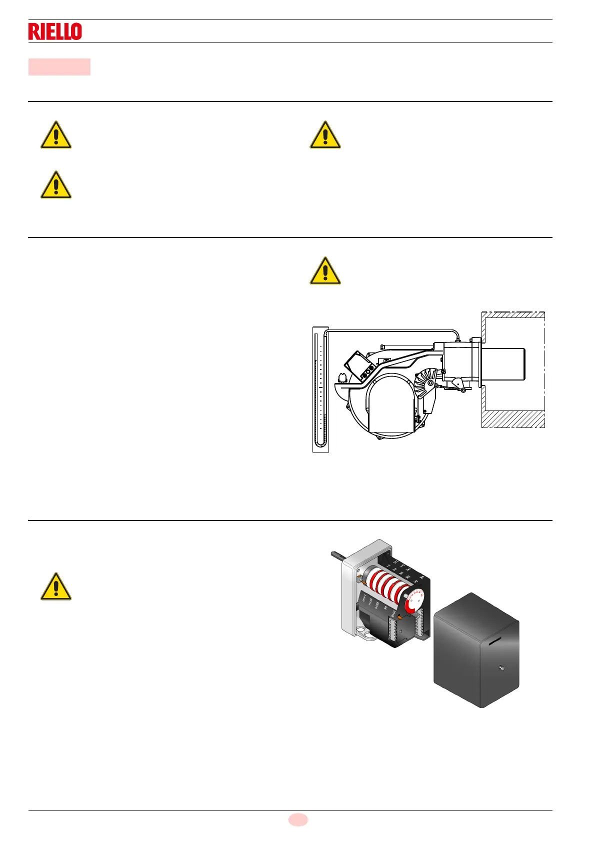
6.3 Servomotor adjustment
The servomotor provides simultaneous adjustment of the air
damper, by means of the variable profile cam and the gas
butterfly valve. The servomotor rotates by 130° in 42 s.
6 Start-up, calibration and operation of the burner
The first start-up of the burner must be carried out
by qualified personnel, as indicated in this manual
and in compliance with the standards and
regulations of the laws in force.
Check the correct working of the adjustment,
command and safety devices.
Before starting up the burner, refer to section
“Safety test - with no gas supply” on page 30.
Before starting up the burner, it is good practice to
adjust the gas train so that ignition takes place in
conditions of maximum safety, i.e. with gas
delivery at the minimum.
Do not alter the factory setting for the 5 cams;
just check that they are as specified below:
Cam I:
130°
Limits rotation toward maximum position.
When the burner is operating at MAX output,
the gas butterfly valve must be fully open: 90°.
Cam II:
0°
Limits rotation toward minimum position.
When the burner is shut down, the air
damper and gas butterfly valve must be
closed: 0°.
Cam III:
20°.
Adjusts the ignition position and the MIN
output.
Cams IV and V: Not used.
 Loading...