21
20154249
Installation
5.13.2 Gas train
Type-approved in accordance with EN 676 and supplied
separately from the burner.
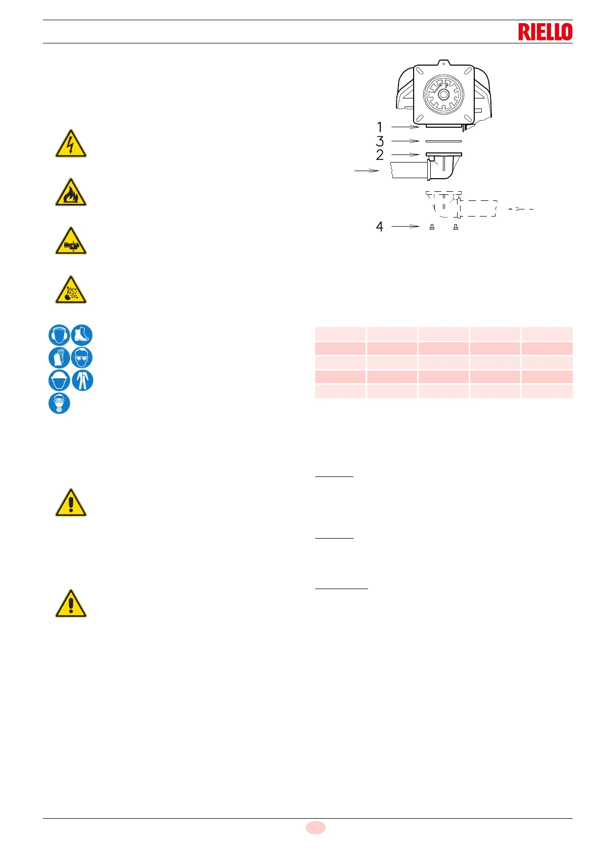
5.13.3 Gas train installation
The train can enter the burner from the right or left side,
depending on which is the most convenient, see Fig. 24.
The gas train must be connected to the gas connection
1)(Fig. 24), using the flange 2), seal 3) and screws 4) supplied
with the burner.
See the accompanying instructions for the adjustment of the gas
train.
5.13.4 Gas pressure
Tab. J indicates the pressure drops of the combustion head and
gas butterfly valve depending on the burner operating output.
Tab. J
The values shown in Tab. J refer to:
– Natural gas G 20 NCV 9.45 kWh/Sm
3
(8.2 Mcal/Sm
3
)
– Natural gas G 25 NCV 8.13 kWh/Sm
3
(7.0 Mcal/Sm
3
)
Column 1
Combustion head pressure drop.
Gas pressure measured at test point 1)(Fig. 25), with:
• combustion chamber at 0 mbar
• burner working at maximum output
Column 2
Pressure drop at gas butterfly valve 2)(Fig. 25) with maximum
opening: 90°.
To calculate
the approximate output at which the burner
operates:
– subtract the combustion chamber pressure from the gas
pressure measured at test point 1)(Fig. 25).
– Find in Tab. J related to the burner concerned, the pressure
value closest to the result of the subtraction.
– Read the corresponding output on the left.
Example with G 20 natural gas:
Maximum output operation
Gas pressure at test point 1)(Fig. 25) = 16.9 mbar
Pressure in combustion chamber = 2.0 mbar
16.9 - 2.0 = 14.9 mbar
A pressure of 14.9 mbar, column 1, corresponds in the table Tab.
J to an output of 2290 kW.
This value serves as a rough guide; the effective output must be
measured at the gas meter.
Disconnect the power supply using the system
main switch.
Check that there are no gas leaks.
Pay attention when handling the train: danger of
crushing of limbs.
Make sure that the gas train is properly installed
by checking for any fuel leaks.
The operator must use the required equipment
during installation.
The gas solenoids must be as close as possible to
the burner to ensure that the gas reaches the
combustion head within the safety time of 3s.
Make sure that the maximum pressure necessary
for the burner is within the calibration range of the
pressure regulator.
Data of head thermal power and gas pressure
refer to operation with gas butterfly valve fully
open (90°).
kW
1 p (mbar) 2 p (mbar)
G 20 G 25 G 20 G 25
1280 9.6 14.3 1.3 2.0
1500 9.7 14.5 1.8 2.7
1800 9.9 14.8 2.7 4.0
2100 12.6 18.8 3.6 5.4
2290 14.9 22.2 4.3 6.4
 Loading...