2903104
22
Start-up, calibration and operation of the burner
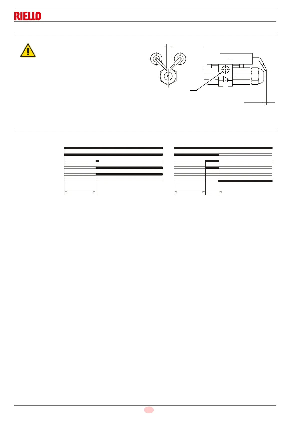
8.6 Electrodes setting
Before removing or assembling the nozzle, loosen the screw (A,
Fig. 19) and move the electrodes ahead.
8.7 Burner start-up cycle
Lock out is indicated by a lamp on the control box (3, Fig. 1 on
page 9)
The position of the electrodes cannot be regulat-
ed. In case of failure, check that the measure-
ments as shown on the figure are respected.
4
±
0.3 mm
D5230
A
2 - 2.5
mm
Fig. 19
~
12s
D5229
~
12s
~
5s
Lock-out due to failure to lightNormal
Fig. 20
Thermostat
Motor
Ignition transformer
Valve
Flame
Lock-out lamp