43
20068428
Start-up, calibration and operation of the burner
The control box will automatically report the same values set at
the points “
P0” and “P1” to points “P2” to “P8”.
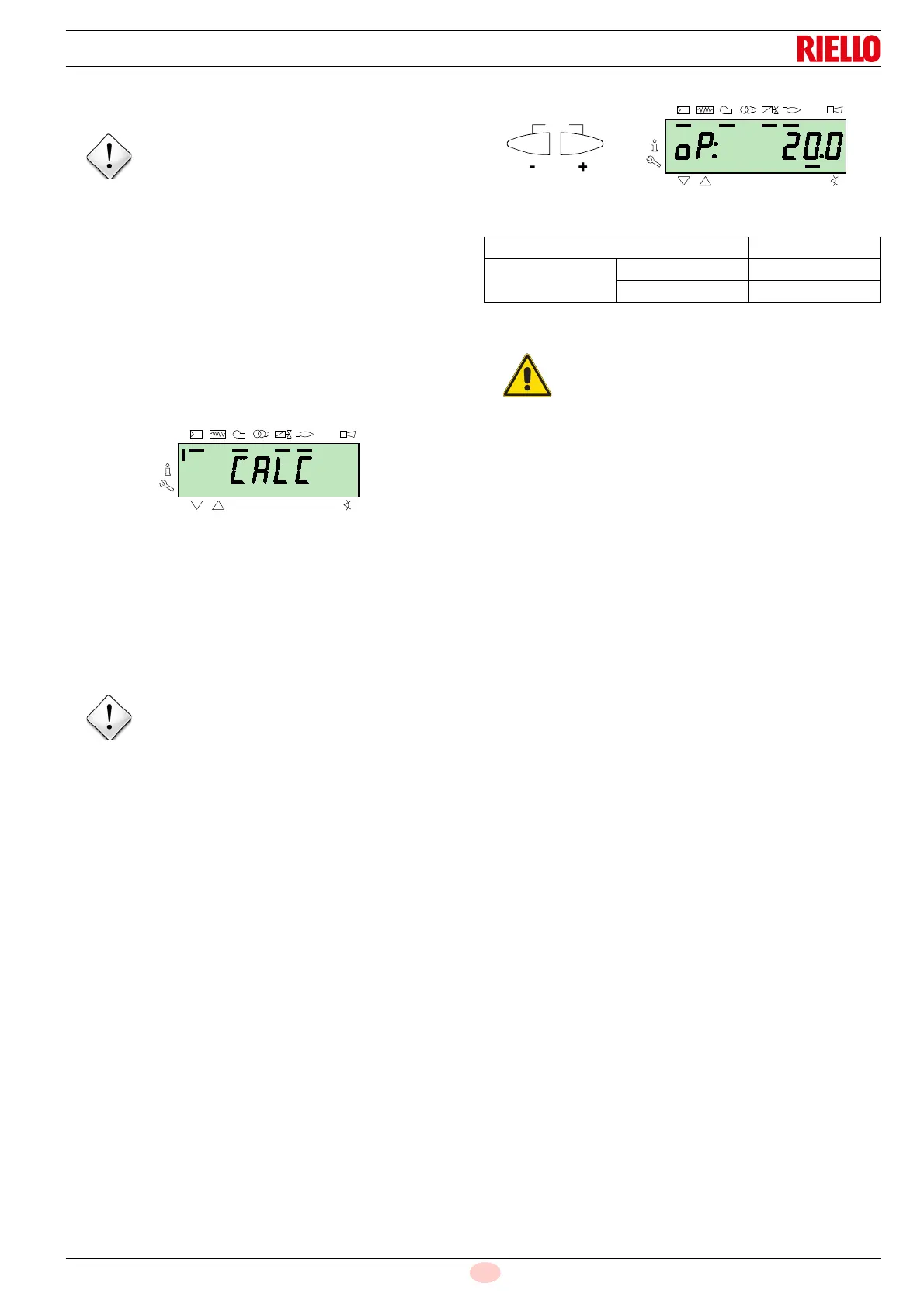
Press the key “
+” until point “P9” has been reached.
Once “
P9” has been reached wait until the display visualises the
flashing indictor “
P9” proposing the same settings as point “P0”.
Now it is possible to change this value to attain the desired max-
imum operating power.
If the gas pressure is too low, despite opening the gas servomotor
to the maximum 90°, it is necessary to use the stabiliser of the
gas valve.
After adjusting point “
P9 keep the key “+” pressed for about 5 sec-
onds, the display shows “
CALC” for a few seconds.
The control box will automatically calculate the points from “
P8”
to “
P2”, distributing them in a line. These are theoretical and must
be checked.
Check that the settings of point “
P8” are adequate.
If not, modify the point.
Proceed in sequence, with the button “
-” , up to point “P1”.
It is possible to modify point “
P1” to obtain a different minimum
modulation point to the ignition point (“
P0”).
During the adjustment of each point, work on the air and gas ser-
vomotors, without modifying the position of the gas valve stabilis-
er.
Halfway through the procedure (i.e. around point
P4 or P5), you
are advised to measure the gas delivery and check that the out-
put is about 50% of the maximum output.
If this is not the case, work also on the gas valve stabiliser: in this
case however, it is necessary to revise the calibrations of all the
points previously set.
Once the calibration of point “
P1” is finished, confirm by simulta-
neously pressing keys “
+” and “-” (ESC): the parameter “546” ap-
pears.
If you want to make the burner work on the entire modulation
curve, press the “
+” and “-” (ESC) keys simultaneously: in this
way, parameter “
546” will automatically be assigned the value of
100% and parameter “
545” will have a value of 20%.
If you want to make the burner work on just a part of the modula-
tion curve, modify parameters “
546” and “545” according to the
"Parameter modification procedure" at page 40.
Simultaneously press the keys “
+” and “-” (ESC) twice, the dis-
play will show the position of the current load.
Factory settings
Tab. S
The purpose is to reach the point “P9” to adjust/fix
the maximum operating power.
Before moving on from one point to the next, wait
for the servomotors to reach the position visual-
ised on the display.
Point of the curve Burner
P0
air 20°
gas 24°
At the end of the "Start-up procedure" it is nec-
essary to carry out a
"Backup", which is used to
memorise the parameters and the data in the con-
trol box inside the RDI21 display …
This operation allows the parameters and the
points of the modulation curve to be restored in
case of problems.
It is advisable to perform a backup every time that
a parameter is changed!
For the procedure refer to the section
"Backup"
at page 44.