43
20163082
Start-up, calibration and operation of the burner
208
Stopping of the program
0 = deactivated
1 = pre-purging (Ph24)
2 = Ignition (Ph36)
3 = Interval 1 (Ph44)
4 = Interval 2 (Ph52)
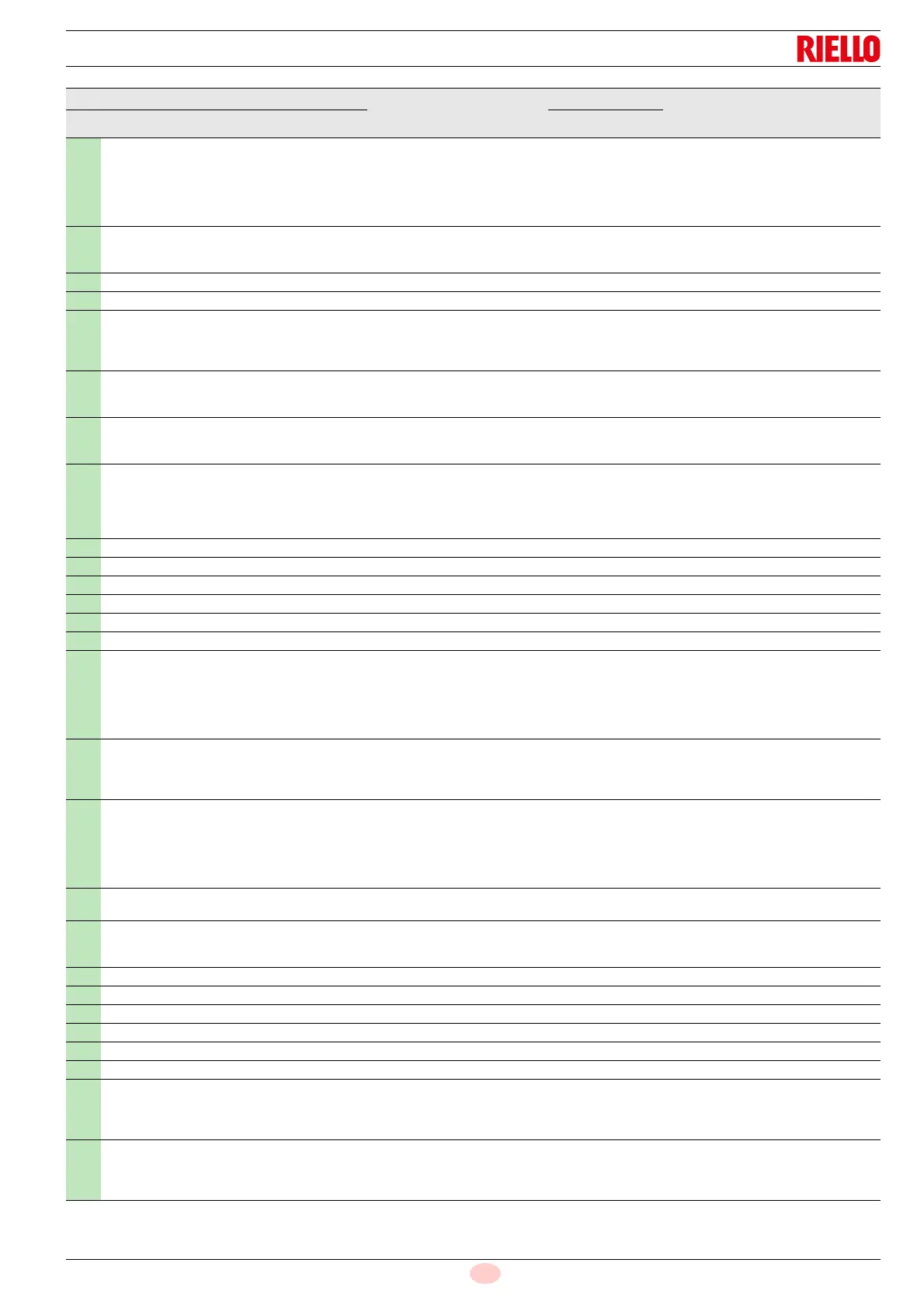
1 - Modification 0 4 1 0 Service Mode
210
Alarm as the pre-purging phase begins;
0 = Deactivated;
1 = Activated
1 - Modification 0 1 1 0 Service Mode
211 Uphill train fan motor 1 s Modification 2s 60s 0.2s 2s Service Mode
212 Maximum time to reach low flame 1 s Modification 0.2s 10 min 0.2s 45s Service Mode
215
Maximum repeats of safety circuit
1 = No repetition
2...15 = Number of repetitions
16 = Constant repetitions
1 - Modification 1 16 1 16 Service Mode
221
Gas: selection of flame sensor
0 = QRB.../ QRC
1 = ION / QRA
1 - Modification 0 1 1 1 Service Mode
222
Gas: Selection of the pre-purging function
0 = deactivated
1 = activated
1 - Modification 0 1 1 1 Service Mode
223
Maximum repeats of minimum gas pressure switch
intervention
1 = No repetition
2...15 = Number of repetitions
16 = Constant repetitions
1 - Modification 1 16 1 16 Service Mode
225 Gas: pre-purging time 1 s Modification 20s 60 min 0.2s 20s Service Mode
226 Gas: pre-ignition time 1 s Modification 0.4 s 60 min 0.2s 2s Service Mode
230 Gas: interval 1 1 s Modification 0.4 s 60s 0.2s 2s Service Mode
232 Gas: interval 2 1 s Modification 0.4 s 60s 0.2s 2s Service Mode
233 Gas: post-combustion time 1 s Modification 0.2s 60s 0.2s 8s Service Mode
234 Gas: Post-purging time (no extraneous light test) 1 s Modification 0.2s 108 min 0.2s 0.2s Service Mode
236
Gas: Minimum gas pressure switch input
0 = deactivated
1 = minimum gas pressure switch (upstream of the
fuel valve 1 (V1))
2 = valve control via the minimum pressure switch
(between fuel vale 1 (V1) and 2 (V2))
1 - Modification 1 2 1 1 Service Mode
237
Gas: Maximum gas pressure switch / POC Input
0 = deactivated
1 = Maximum gas pressure switch
2 = POC
1 - Modification 1 2 1 1 Service Mode
241
Gas: Valve leak detection test
0 = test deactivated
1 = valve leak detection test at start up
2 = valve leak detection test at shutdown
3 = valve leak detection test at start-up and at shut-
down
1 - Modification 0 3 1 2 Service Mode
248
Gas: Post-purging time (t3)(at deactivation of the load
(LR)) - ON
1 s Modification 1s 108 min 0.2s 1s Service Mode
261
Oil: selection of flame sensor
0 = QRB.../ QRC...
1 = ION / QRA...
1 - Modification 0 1 1 0 Service Mode
265 Oil: pre-purging time 1 s Modification 15s 60 min 0.2s 15s Service Mode
266 Oil: pre-ignition time 1 s Modification 0.6s 60 min 0.2s 2s Service Mode
270 Oil: interval 1 1 s Modification 0.4 s 60 min 0.2s 2s Service Mode
272 Oil: interval 2 1 s Modification 0.4 s 60 min 0.2s 2s Service Mode
273 Oil: post-combustion time 1 s Modification 0.2s 60s 0.2s 8s Service Mode
274 Oil: Post-purging time (no extraneous light test) 1 s Modification 0.2s 108 min 0.2s 0.2s Service Mode
276
Oil: Minimum input oil pressure switch
0 = deactivated
1 = activated from phase 38
2 = activated from safety time (TSA)
1 - Modification 1 2 1 1 Service Mode
277
Oil: Maximum oil pressure switch / POC Input
0 = deactivated
1 = Maximum oil pressure switch
2 = POC
1 - Modification 1 2 1 1 Service Mode
Parameter
No. of
elements
Unit of
measure-
ment
Modifica-
tion
Values interval
Degree of
precision
Predefined
setting
Access mode
No. Description Min. Max.



 To Next Page