22
INSTALLATION
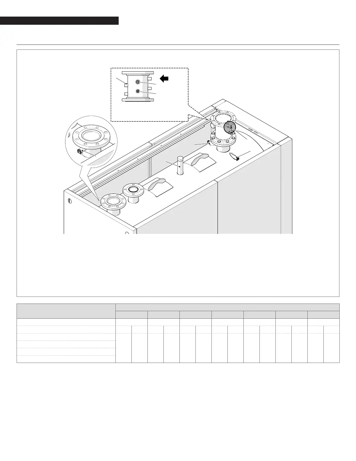
2.8 Positioning of sensor sockets
RTC 1000-80 ÷ RTC 4700-80
2
1
4
(*)
3
a) 3/4"NPT
b) 1/2" NPT
a
a
a
b
b
b
LWCO
5
6
7
(*) On the models RTC 3000-80 to RTC 5500-80 the safety tting is anged.
1 Outlet operating temperature thermowell (G 1/2") for n.2÷3 instrument bulb. Internal diameter probe sockets 7 mm. Thermow-
ell length L170 mm
2 Over-temperature protection thermowell (G 1/2") for n.1 instrument bulb. Internal diameter probe sockets 15 mm. Thermowell
length L170 mm
3 Inlet operating temperature thermowell (G 1/2") for n.2÷3 instrument bulb. Internal diameter probe sockets 7 mm. Thermowell
length L100 mm
Boiler
RTC-80
1000 1300 1700 2300 3000 3800 4700
Sensor manifold type Ø NPS 2-1/2" #150 3” #150 4” #150 4” #150 5” #150 5” #150 6” #150
Thermowell length (*) min. max. min. max. min. max. min. max. min. max. min. max. min. max.
4 - LWCO (3/4" NPT)
2-31/64”
63 mm
3-15/16”
100 mm
2-31/64”
63 mm
3-15/16”
100 mm
2-31/64”
63 mm
3-15/16”
100 mm
2-31/64”
63 mm
3-15/16”
100 mm
2-31/64”
63 mm
4-59/64”
125 mm
2-31/64”
63 mm
4-59/64”
125 mm
2-31/64”
63 mm
4-59/64”
125 mm
5 - Gauge (3/4" NPT)
6 - Manual reset high limit (3/4" NPT)
7 - Outlet temperature sensor (1/2" NPT)
(*) The sensor sockets are not supplied.
9
The LWCO must be installed in a position higher than all other regulation and safety devices (over-temperature protection, operating
temperature sensor and temperature gauge).