27
INSTALLATION
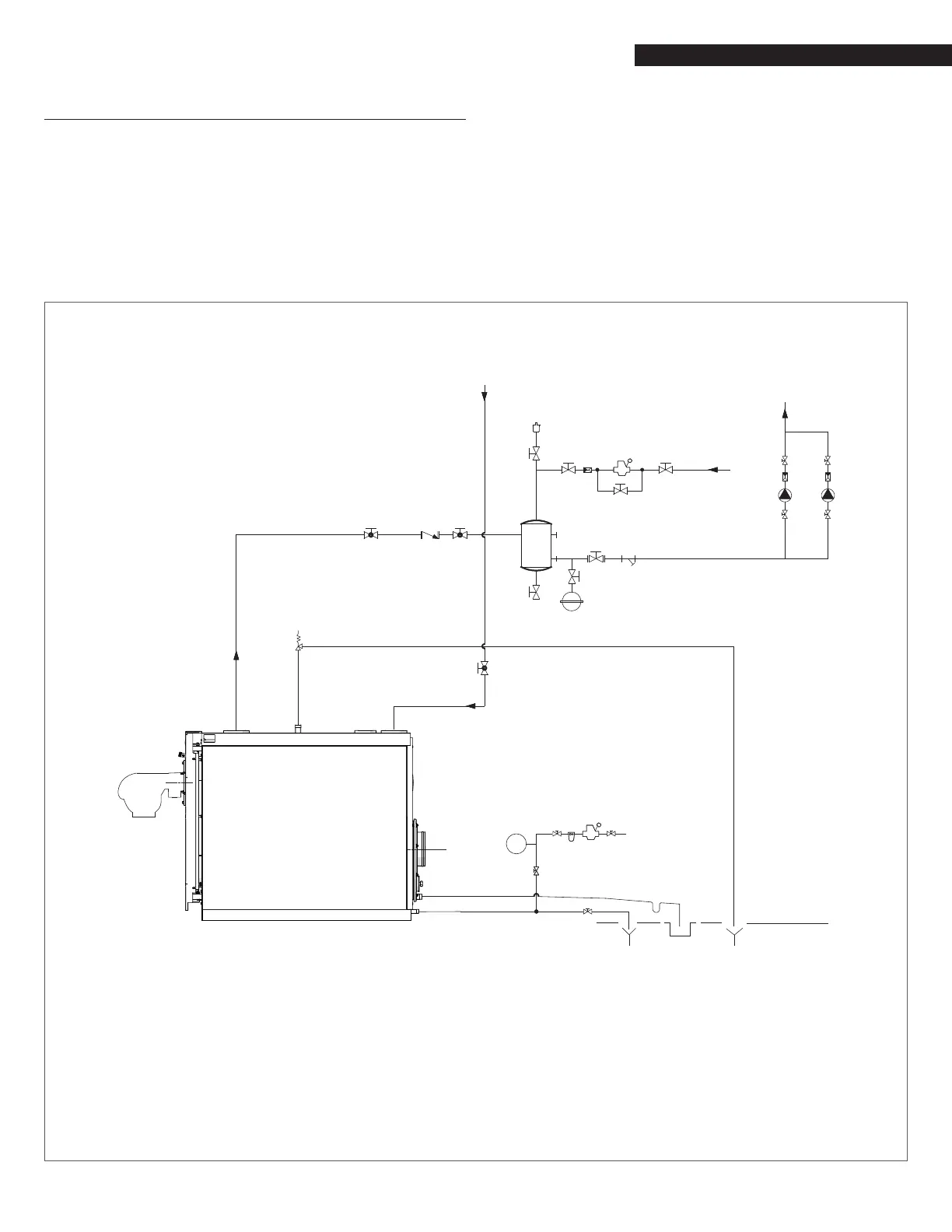
2.9 Typical water system schematics
The following P&ID represent the typical arrangements for the
most common types of installation and they are only a suggestion
for the installer that is resposible for all equipment and details
required by local laws.
9
The DHW and central heating circuits must incorporate ex-
pansion vessels of adequate capacity as well as suitably rated
safety valves. The condensate drain must be connected to a
suitable collection and drain system.
9
The selection and the installation of the components of the
system is the responsibility of the installer, who must operate
in accordance with good practice and current Legislation.
9
If needed, water supplies and recovery circuits must be condi-
tioned by suitable treatment systems. Refer to the values list-
ed in the table in the paragraph Water quality requirements.
0
CAUTION: It is prohibited to operate the circulators without
water.
Single Boiler Piping Schematic Type A
RTC 1000-80 ÷ RTC 4700-80
15
6
3
3
3
11
3
3
3
3
13
16
16 1617
10
9
7
5
3
5
4
3
3
4
3
18
15
10
12
3
3
3
8
LT (*)
CENTRAL
HEATING
RETURN
HEATING
SUPPLY
MAKE-UP
WATER
LT RETURN
FLOW
WATER
INLET
1
19
2
1 Boiler
2 Burner
3 Isolation valves
4 Central heating system pump
5 Non-return valves
6 Automatic vent valve
7 Boiler safety valve
8 Boiler drain valve
9 Y strainer
10 Pressure reducer
11 Expansion tank
12 Water softener lter
13 Siphon
14 Condensate outlet
15 Drain
16 Isolation valve
17 Non-return valve
18 Air separator
19 Pressure gauge
HT High Temperature
(*) LT Low Temperature