7
GENERAL
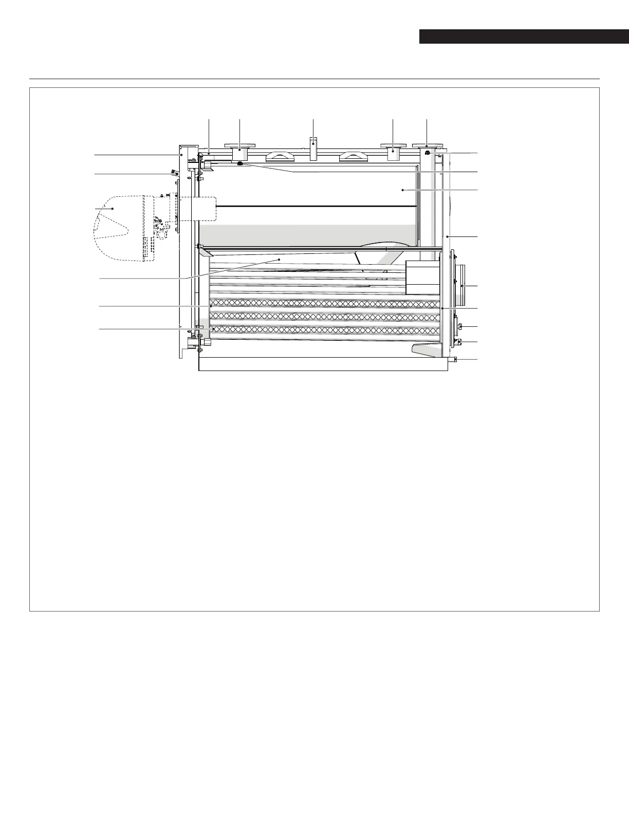
1.5 System layout
1
2
17
18
19
3
11
9
10
10
12
13
14
16
15
1 Burner
2 Flame inspection window with pressure measurement
point
3 Door
4 Casing
5 Outlet
6 Safety device tting
7 Heating return (high temperature)
8 Heating return (low temperature)
9 Blind plug
10 Instrument bulb/sensor sockets
11 Combustion chamber
12 Flue gas exhaust
13 Flue gas box
14 Inspection window
15 Condensate outlet
16 Boiler drain
17 Turbulators
18 Flue gas pipes
19 Second ue pass
(*) On the models RTC 3000-80 to RTC 5500-80 the safety tting (6) is anged.
(**) On the RTC 5500-80 the low temperature heating return (8) is located at the rear of the boiler.