12
5 – reference impedance selection for SWR measurement: 50 or 75 Ohm;
6 – select series or parallel model of load;
0 – go to the third page of settings which contains various test commands used
for fast checking of the entire analyzer.
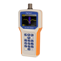
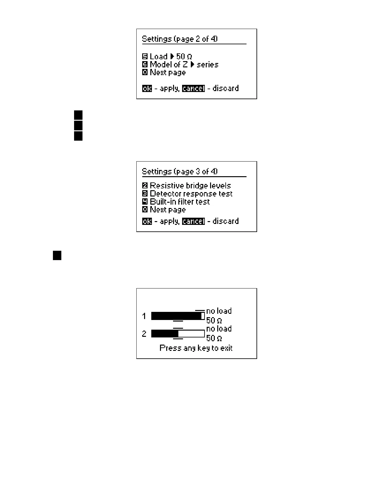
2 – RF bridge test. With no load at the antenna connector, the display should look
like shown on the picture:
For the 50-Ohm load, the filled bars should stand at corresponding positions (notice
the “no load” and “50 Ω” marks):