Appendix B 18
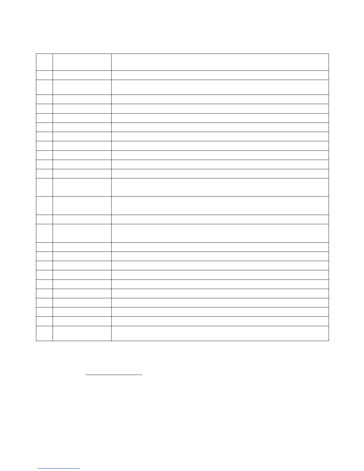
25-pin transceiver connector pinout
Pin
Pin name Description
1 FSK_OC FSK open-collector output
14
FSK_PULLUP
Pullup to +5V through 4.7K resistor
2 - Not used
15 - Not used
3 VCC +5V output (USB power line)
16 PTT5V TTL-level PTT output (5V in transmit, 0V in receive mode)
4 CW_OC Open-collector CW output
17 PTT_OC Open-collector PTT output
5 SQ Squelch input, 4.7K resistor pullup to +5V
18 12V_MAX +12V output (generated by MAX232 chip)
6 SPK_TRCVR2 Transceiver audio output (speaker), sub receiver
19 RXD_OE Serial input (5V levels), connect RXD5V to VCC to activate this
input
7 CIV_IN CI-V input (ICOM transceivers), pulled up to 12V_TRCVR with
4.7K resistor
20 12V_TRCVR Connect to VCC to power the CIV_IN input
8
CIV_OUT
CI-V open-collector output (ICOM transceivers), connect to
CIV_IN
21 CO_PULLUP Pullup to +5V through 4.7K resistor
9 TXD12V RS-232-compatible serial output (±12V levels)
22 RXD12V RS-232-compatible serial input (±12V levels)
10 TXD5V Serial output (5V levels)
23 RXD5V Serial input (5V levels)
11 GND Digital ground
24 GND Digital ground
12 SPK_TRCVR Transceiver audio output (speaker), main receiver
25 MIC_TRCVR Transceiver audio input (microphone)
13 AGND_TRCVR
Audio signal ground
For transceiver cable design guide and cable diagrams for most popular transceivers,
please see the www.rigexpert.ua website.