Communications Manual Rev 3.10 Software Versions 3.xx
Page 6
003R-618-310
2. Connecting to the Instrument
2.1. opto-LINK
A temporary infrared com-
munications link can be
established between any
instrument and a PC using
an optional opto-LINK cable.
The opto-LINK cable can be
used to transfer setup
information from a PC and
download software upgrades
to the instrument. This setup
information can be stored for
later use and/or transferred
to other instruments.
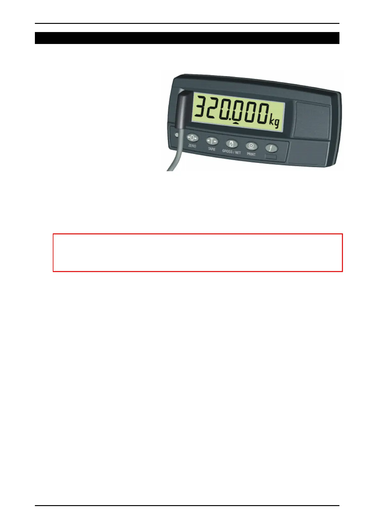
The PC end of the opto-LINK cable is a standard COM port (female DB9)
connector. The instrument end of the cable consists of an infrared transceiver,
which attaches to the left side of the instrument display. To facilitate a quick and
simple connection, the infrared transceiver is secured in place by a permanent
magnet located within the head of the opto-LINK.
WARNING
The opto-LINK head contains a strong magnet and care should be taken with
its proximity to electronic media (eg. credit cards, floppy disks, etc.) and/or
other electronic instrumentation.
Note: The serial connection for the opto-LINK is standard to this instrument.
2.1.1. opto-LINK Activation
This feature is used to temporarily connect a PC to the instrument for calibration
and setup purposes.
A long press of the GROSS/NET key will toggle the opto-LINK infrared
communications On/Off.
When the opto-LINK has been enabled the following will occur:
• The instrument briefly displays the prompt opto-L.
• The editing annunciators (ie. GRP, ITM, etc.) will flash while the instrument
searches for activity. During this period, the instrument also disables the RS-
232 communications.
• Activity Located: If the instrument is successful in locating activity, the editing
annunciators will continue to flash during the entire period of communications.
• No Activity Located: If the instrument fails to locate activity in five minutes,
the opto-LINK will be disabled and the editing annunciators will stop flashing.
The instrument will also revert back to the normal RS-232 communications (ie.
the SERIAL:TYPE setting will be re-activated).
2.1.2. opto-LINK Communications Settings
The communications settings for opto-LINK are 9600 baud, no parity, 8 data bits
and 1 stop bit. This is often referred to as 9600 N81.