Trainer 40 Instructions
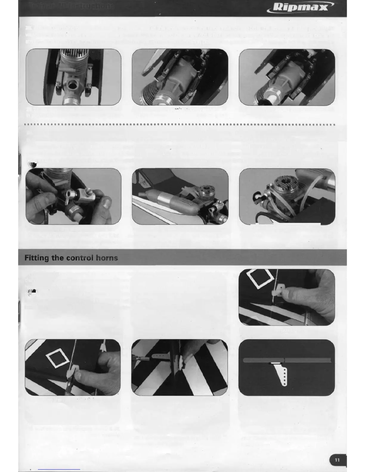
29. Add the clamping plates and screws to either side of the engine. From the underside, thread onto the screws a shake proof
washer and nut. Tighten the screws evenly so that the clamping plates are not distorted and ensure that the engine remains pointing
straight. Finally, add the remaining nuts to each of the screws and tighten in position.
29.1 Clamping plates and screws
in position
29.2 Adding the shake proof washer
and nut
29.3 Lock nuts added and tightened
30. The engine's throttle is controlled by the movement of a pushrod located in the front, upper part of the fuselage. Thread the
pushrod's Z bend into a hole in the carburettor's throttle arm and, following the engine manufacturer's instructions, secure the
carburettor to the engine. Attach also the engine's silencer, ensuring the holding screws are well tightened. Trim to length and
connect the fuel tank's clunk tank outlet to the engine^ carburettor and the fuel tank's upper vent to the silencer's pressure nipple.
T^remaining fuel tank outlet is the filling port and the tubing is simply sealed using a suitable clean screw.
30.1 Attaching the pushrod Z bend to
the throttle arm
30.2 Securing the engine's silencer
in place
30.3 Connecting the fuel tubing to
the engine
31. Looking from the rear of the model, the rudder horn is fitted on the left hand side of
the rudder at a position approximately 25mm from the base of the rudder. Hold the
horn in place on the rudder, aligning the horn clevis holes with the rudder hinge centre
lir ^pbnd drill through the horn mounting holes into the rudder with a 2mm drill. Secure
the horn in position with two 11 mm long self tapping screws which pass through the
horn, into the rudder and into the horn backing plate.
31.2 Drilling the rudder for fixing screws
31.3 Securing the horn to the rudder
using two screws and backing plate
31.1 Rudder horn position
31.4 Position horn holes in line with
control surface hinge