Trainer 40 Instructions
Installing the throttle pushr
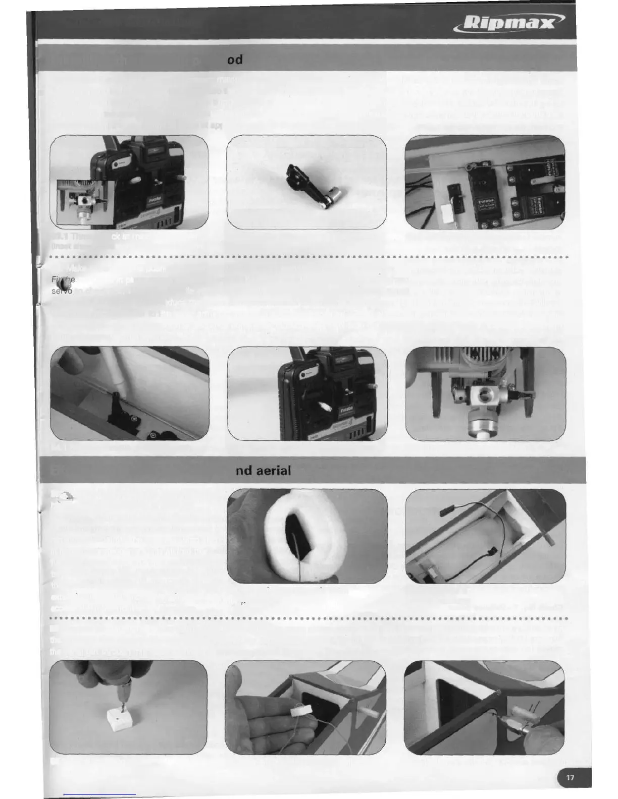
53. Position the throttle servo to represent maximum throttle by switching on the radio equipment with the throttle stick fully
upwards and trim lever at neutral. Check too that the servo moves in the correct direction to close the throttle. Switch off and
disconnect the throttle servo. Prepare the throttle servo arm by attaching a connector, in a similar way to the nose leg arm, at a
distance approximately 16mm from centre. Trim off any unused arms. Push the throttle to fully open, thread the connector onto the
pushrod and fit the arm onto the servo at approximately 45 degree angle, facing forwards.
53.1 Throttle stick at maximum power
(Inset shows corresponding throttle position)
53.2 Throttle servo arm with connector
in place
53.3 Servo arm at 45 degrees
54. Make a mark on the pushrod wire approximately 8mm beyond the connector, remove the arm and cut the pushrod to the mark,
arm back in place onto the pushrod and in the same position on the servo and tighten the connector grub screw. Operate the
to check that when the throttle stick is in the fully down position the carburettor throttle is almost closed without stalling the
servo. If it is not possible to reduce the servo arm movement to prevent this happening using the transmitter, the connector will
have to be moved closer to the servo arms centre and the process repeated. Check also that, by moving the throttle stick trim lever
fully downward, the engines throttle becomes completely closed, which will stop the engine if desired. Finally, secure the servo arm
using the manufacturer's screw.
54.1 Marking throttle pushrod length
54.2 Throttle stick at minimum power
54.3 Throttle in closed position
Fitting the battery, receiver a
5Fia?'ug the receiver battery into the switch
harass, wrap the battery in foam for
protection and install it into the fuselage just
behind the fuel tank. Connect all the
remaining leads into the receiver, wrap also
* in foam for protection and install into the
fuselage between the fuel tank and servo
tray. The receiver aerial should be lead out of
the receiver in a direct route and the aileron
55.1 Receiver wrapped in foam
extension lead and battery charging lead left f
or
n
ro
tection
accessible in the front of the fuselage.
55.2 Receiver and battery installed in
front of fuselage
56. Prepare an aerial pull stop by drilling two 2mm holes in a piece of the repair wood and thread the aerial into it. Drill a 2mm hole in
the fuselage side close to the rear wing dowel for the aerial outlet. With the pull stop remaining on the inside of the fuselage, lead
the aerial out through this hole, leaving the minimum of aerial between the receiver and pull stop.
56.1 Aerial pull stop
56.2 Aerial threaded through pull stop
56.3 Drilling a 2mm hole for the aerial outlet