Trainer 40 Instructions
Fitting the fuel tank
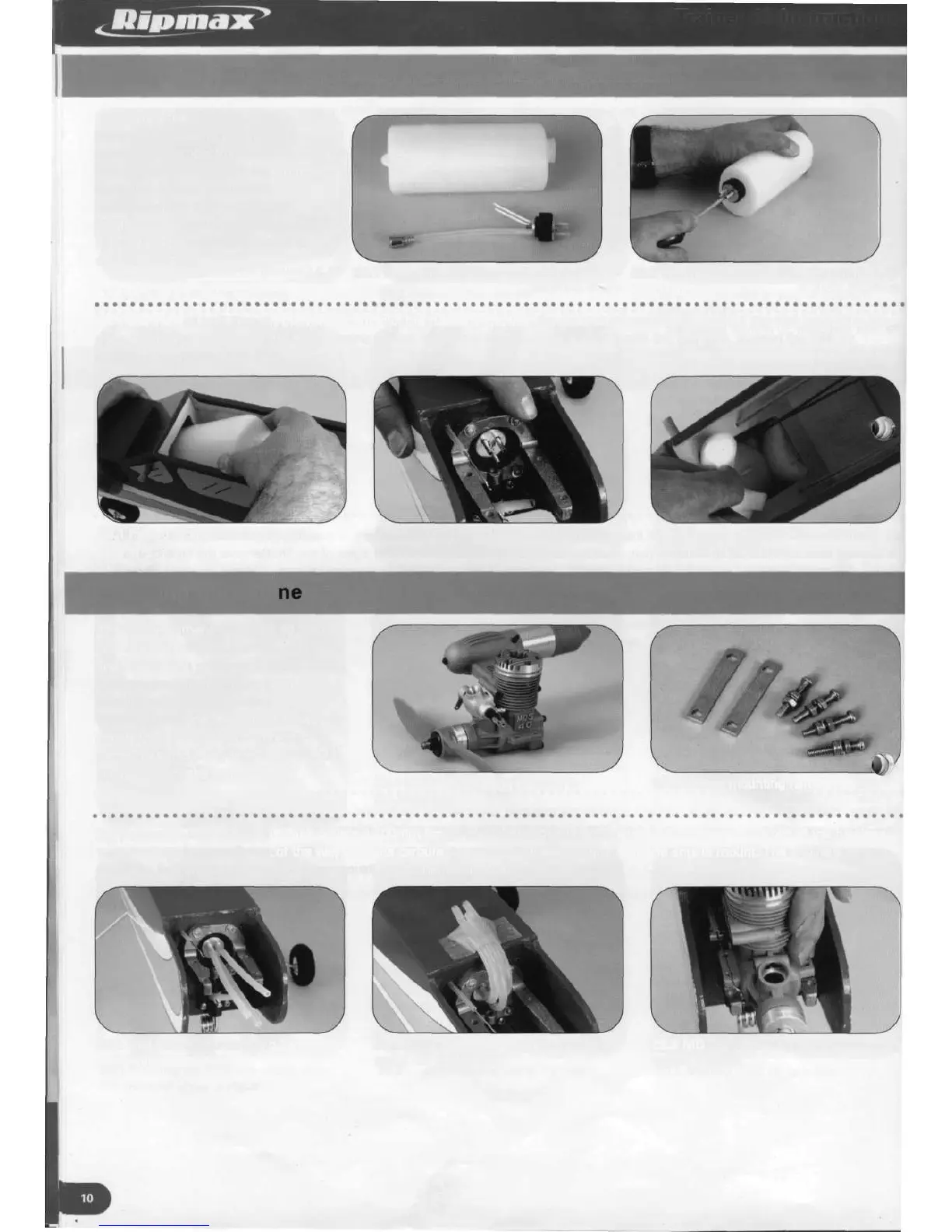
25. Identify the fuel tank and its
hardware. Following the diagrams
included, assemble the fuel tank
ensuring that the clunk is free to move
from side to side and up and down. This
will ensure that fuel is delivered
to the engine regardless of the model's
attitude. Tighten the bung screw to
seal the fuel tank.
25.1 Fuel tank and clunk assembly 25.2 Sealing the fuel tank by tightening
the bung screw
26. Pass the fuel tank through the wing opening in the fuselage and into the nose of the model, the neck of the tank protruding into
the opening at the centre of the metal engine mount. Using the foam packing supplied with the fuel tank, support the tank by
packing it around the tank bay.
26.1 Pass the tank into the fuselage
Installing the engi
26.2 Fuel tank neck protruding through
engine mount former
26.3 Support the fuel tank using the
foam packing supplied
27. We recommend the MDS 40 PRO
two stroke engine for powering the
Trainer 40. This powerful, easy to handle,
quiet engine will give many hours of
trouble free, smooth running.
Identify the engine mounting hardware
consisting of two metal clamping
plates, four mounting screws, four shake
proof washers and eight nuts.
27.1 MDS 40 PRO engine used in
the prototype
27.2 Engine mounting hardware
28. Connect to each of the fuel tank outlets a 100mm length of fuel tubing. Their free ends can be taped to the top of the fuselage
to keep them temporarily out of the way. With its carburettor removed, place the engine in the engine mount. The engine's
mounting lugs should sit over the grips moulded into the mount.
28.1 Fuel tubing connected to fuel 28.2 Fuel tubing free ends temporarily 28.3 MDS 40 PRO engine in position on
tank outlets taped out of the way engine mounts