Trainer 40 Instructions
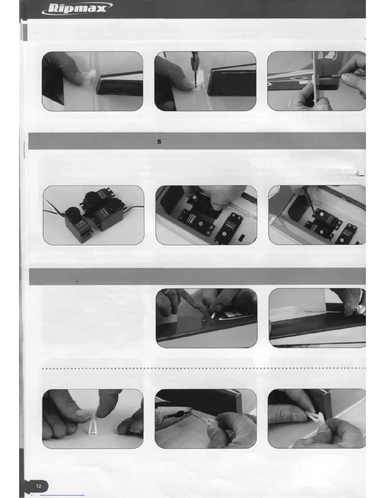
32. Looking from the rear of the model, the elevator horn is fitted on the right hand underside of the elevator. It should be held at a
distance of approximately 20mm from the centre of the model, with the horn clevis holes aligned with the elevator centre line. Usinc
a 2mm drill, drill the elevator for the securing screws. Secure the horn in position in a similar way to the rudder horn.
32.1 Elevator horn position 32.2 Drilling the elevator for
fixing screws
32.3 Securing the horn to the elevator
using two screws and backing plate
I
Installing the fuselage servo
33. Following the manufacturer's instructions, fit the rubber servo mounting grommets and brass ferrules supplied with the radio
equipment to the elevator, rudder and throttle servos and remove the two wooden pushrods from the fuselage. The servos are
mounted in a ply tray pre-installed in the fuselage. Observe the photograph showing the servo arrangement and install the server^
into the plywood tray. Drill 1.5mm pilot holes for the four securing screws supplied with each servo and screw the servos in placer
33.1 Arrangement of rudder, elevator
and throttle services
33.2 Install the servos, allowing their leads
to pass underneath the tray towards the
throttle servo
33.3 Drill 1,5mm pilot holes for the
securing screws and screw in place
Installing the elevator pushrod
34. Locate the slot for the elevator pushrod
(on the right hand side of the fuselage,
looking from the rear) and cut through and
remove the covering. Note that the elevator
pushrod is the longer of the two wooden
pushrods. Insert the threaded end of the
pushrod through the fuselage opening at
the wing position, down into the fuselage
and out through the slot.
34.1 Cutting through and removing the
covering material from the pushrod slot
34.2 Threaded end of pushrod passed
through slot
35. Fit a plastic clevis keeper onto a clevis and screw the clevis onto the pushrod. Open the clevis and snap it in place into the
middle hole of the elevator horn.
35.1 Fitting clevis keeper onto
a clevis
35.2 Threading clevis onto end
of pushrod
35.3 Clevis snapped into middle hole of
elevator horn