Trainer 40 Instructions
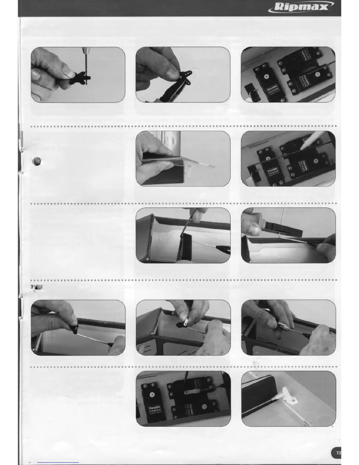
36. Centre the elevator servo by switching on the radio equipment with the sticks centralised and trim levers at neutral. Switch off
and disconnect the servo. Using a 2mm drill, open out the hole in a servo arm which corresponds approximately to 11mm from
centre. Trim off any unused sides of the arm and position it on the servo in line with the width of the fuselage.
36.1 Open out with a 2mm drill the hole
in the servo arm corresponding to 11mm
from centre
36.2 Using side cutters, cut off any
unused arms
36.3 Servo arm in place aligned with
width of fuselage
37. With the elevator held at neutral, mark
the wire where it passes over
the hole in the servo arm.
37.1 Elevator held at the neutral position
37.2 Mark the wire where it passes over
the hole in the servo arm
38. Release the clevis from the horn
and pull the pushrod clear from the
fuselage a sufficient distance to allow
a 90 degree bend to be formed at the
marked position. Cut off any excess
wire to leave 6mm of pushrod after
the bend.
38.1 90 degree bend formed at
marked position
38.2 Cut off excess wire to leave
6mm of pushrod beyond the bend
emove the arm from the elevator servo and thread it over the bend formed on the pushrod followed by a swing keeper,
sniping the keeper into place.
39.1 Servo arm threaded onto pushrod
39.2 Swing keeper in place on pushrod 39.3 Swing keeper snapped over pushrod
40. Replace the arm onto the elevator
servo, securing in place with the
radio manufacturer's screw. Re-attach
the clevis and slide the clevis keeper
closer to the horn.
40.1 Servo arm secured in place with 40.2 Clevis replaced and clevis keeper in
manufacturer's screw final position