Trainer 40 Instructions
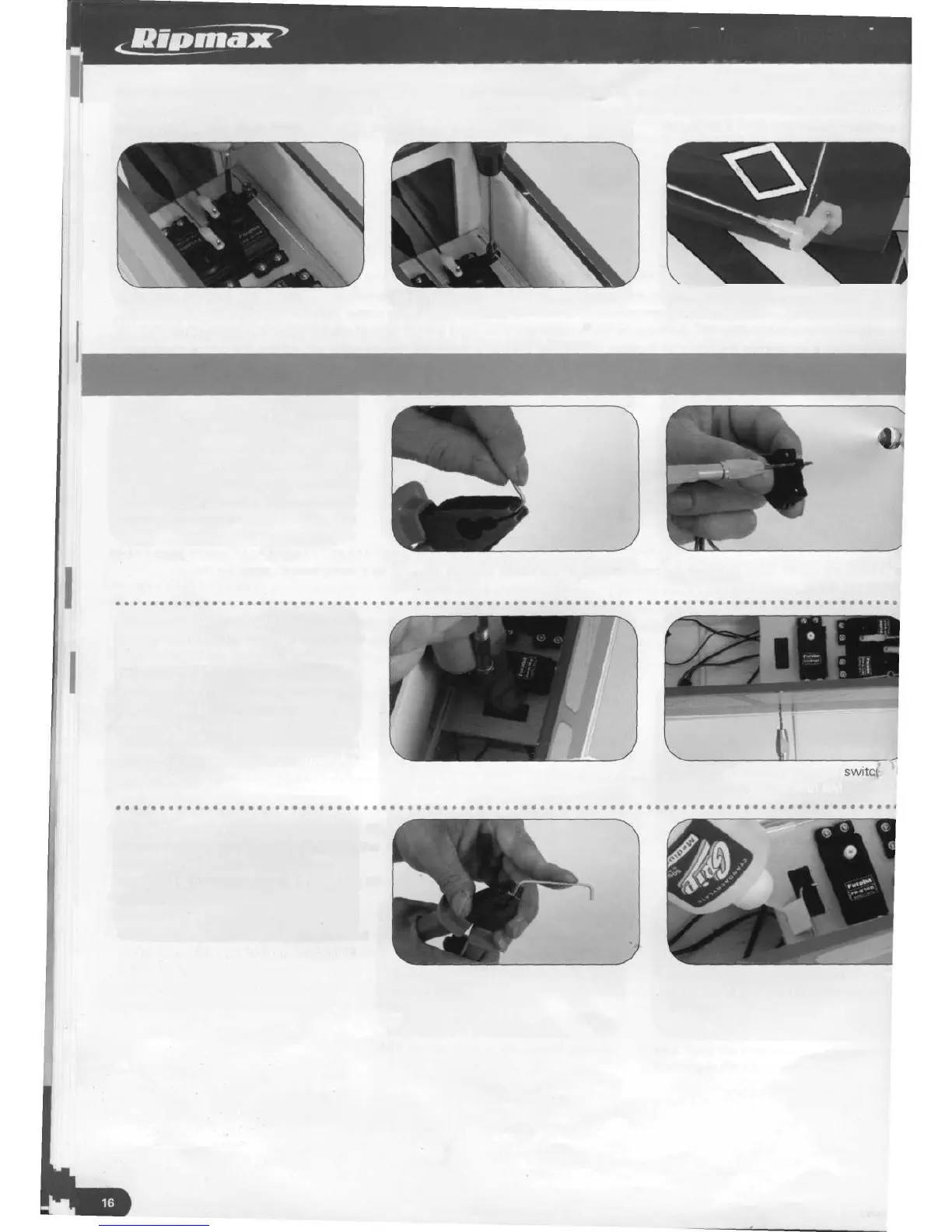
49. Pass the pushrod again through the connector and replace the arm onto the servo, securing in place with the radio
manufacturer's screw. With the wheel held centred, tighten the grub screw of the connector onto the pushrod. Re-attach the rudder
clevis and slide the clevis keeper closer to the horn.
49.1 Nose leg pushrod through
connector and securing servo arm in
place with manufacturer's screw
49.2 Tightening connector grub screw
with wheel centred
49.3 Clevis replaced and clevis keeper
in final position
Installing the receiver switch
50. Form the switch operating arm from
one of the discarded pieces of wire
pushrod. Bend a 90 degree bend of
approximately 8mm length on one end of
the wire. Check the fit of the wire in the
hole in the switch and if necessary open
out the hole to suit.
50.1 Bending the first bend of the switch
operating wire
50.2 Open out the hole in the switch to
suit the wire
51. Place the backing plate of the switch
over the remaining rectangular hole in the
servo tray and use it to drill two, 2mm
holes for the switch mounting. Pass the
switch from the underneath into the tray
hole, add the backing plate and secure in
place with the two screws supplied.
Drill a suitable hole for the operating arm
wire in the fuselage side in line with the
switch side.
52. On the other end of the wire make a 45
degree bend, facing towards the rear of the
model, to form a grip. Pass the wire
through the fuselage side and thread the 90
degree bend into the hole in the switch.
The wire is prevented from becoming
detached by gluing a repair piece of wood
onto the tray, allowing it to rest against the
wire. Ensure the switch operates
smoothly and that it follows convention by
arranging the operating arm to push for 'on'
51.1 Using the switch backing plate to
drill the two mounting holes
51.2 Drilling fuselage side for ^
operating arm in line with switch side
52.1 45 degree bend formed on other
end of wire
52.2 Scrap piece of wood glued to tra
to prevent the operating arm becomir
detached