Trainer 40 Instructions
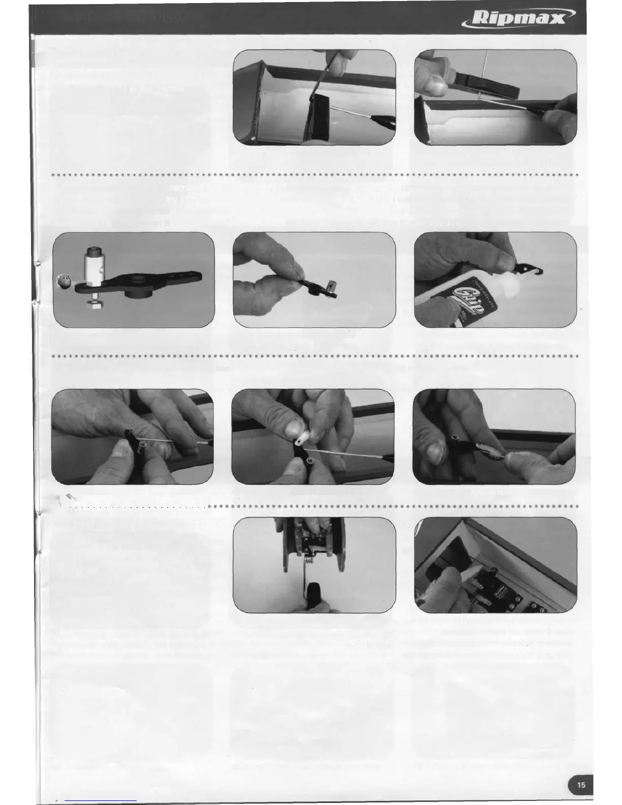
45. Release the clevis from the horn and
pull the pushrod clear from the fuselage
a sufficient distance to allow a 90 degree
bend to be formed at the marked
position. Cut off any excess wire to
leave 6mm of pushrod after the bend.
45.1 90 degree bend formed at
marked position
45.2 Cut off excess wire to leave
6mm of pushrod beyond the bend
46. Remove the servo arm. Unscrew the grub screw from the centre of an adjustable connector and attach the connector to the
rudder servo arm approximately 11mm from the centre and on the opposite side to the rudder pushrod. Only tighten the screw into
the first nut an amount to allow the connector to freely rotate and then apply a small drop of medium cyanoacrylate and add the
second lock nut and tighten the two nuts together. Check that the connector is still free to rotate and replace the central grubscrew.
46.1 Connector illustration
46.2 Connector fitted to rudder
control horn
46.3 Small drop of medium cyanoacrylate
applied together with locknut
47. Thread the rudder servo arm over the bend formed on the rudder pushrod followed by a swing keeper, snapping the
keeper into place.
47 J Servo arm threaded onto pushrod
..#
47.2 Swing keeper in place on pushrod
47.3 Swing keeper snapped over pushrod
48. Thread the steerable nose leg
pushrod through the adjustable
connector, at the same time replacing
the arm onto the rudder servo. With the
nose wheel held centred, mark the
pushrod at a position 8mm beyond the
adjustable connector. Remove the servo
arm and cut the pushrod to the
marked line.
48.1 Nose wheel held centred 48.2 Marking nose leg pushrod position