Trainer 40 Instructions
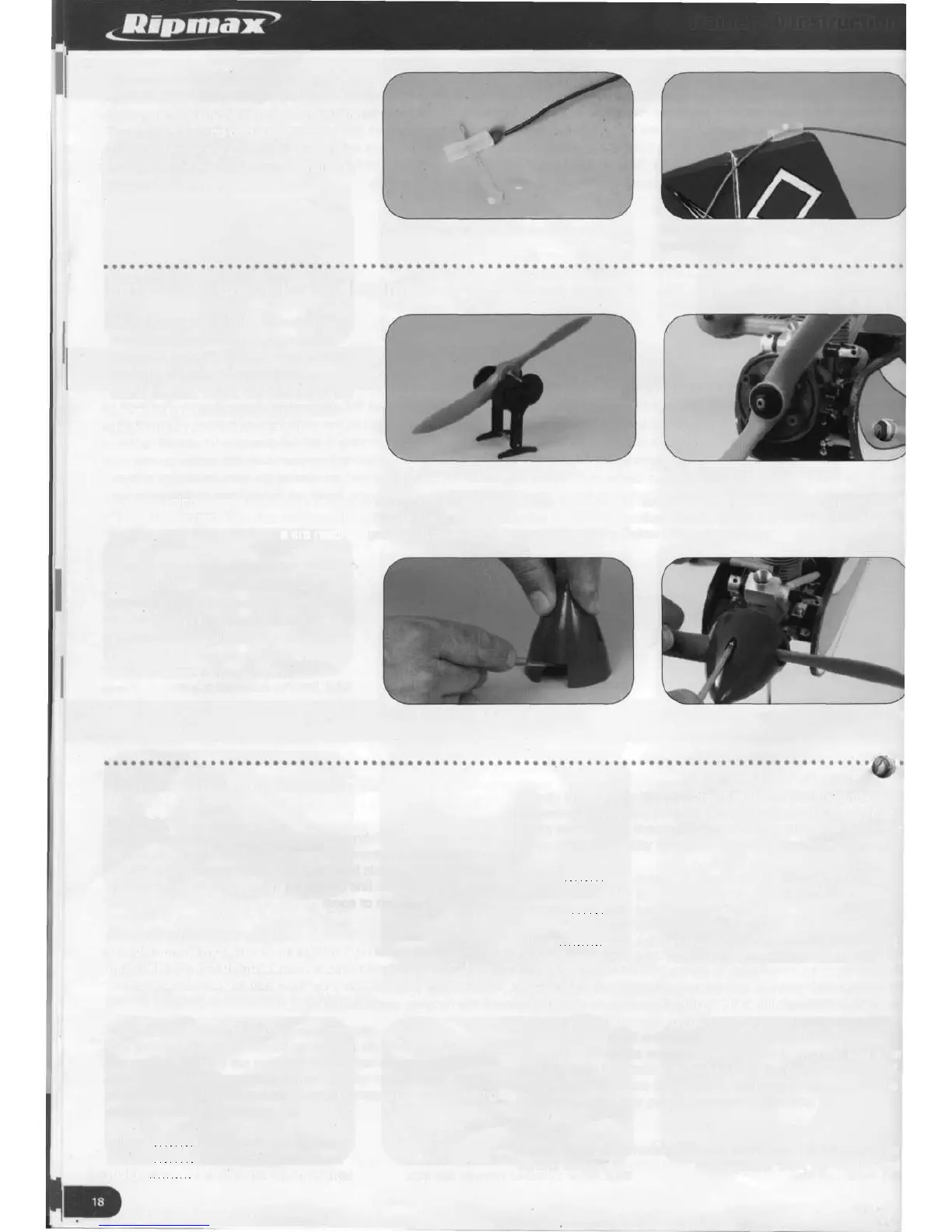
57. Cut a piece of fuel tubing to
approximately 20mm length and push a
safety pin through the centre of the tubing.
Thread the free end of the aerial down the
tubing between the pin and push the pin
into the top of the fin. Pull the aerial tight
and push the pin firmly into the tubing.
\
\
57.1 Safety pin pushed through tubing 57.2 Aerial threaded into tubing and
pinned to fin
Fitting the propeller and spinner
58. Following the engine manufacturer's
recommendations, choose a propeller
suitable for both the engine and model
(typically a 10X6 with a 40 size two
stroke engine). Check the balance of the
propeller and if necessary lightly sand
the heavy blade to achieve a balance.
58.1 Checking propeller balance
58.2 Backplate location pegs
Push the spinner backplate onto the engine shaft followed by the propeller, washer and nut. As the compression resistance is felt, it
will feel more natural to flick the propeller with the blade tightened in the 12 o'clock position. Before tightening the nut check that
the two pegs of the backplate are resting against trailing edge of the propeller blade. Tighten the nut securely.
59. Fit the spinner using the two screws
provided. Depending on the make of
propeller, it may be necessary to trim
the cut outs in the spinner to allow
the spinner to locate into the backplate.
Tighten the screws securely and check
that the assembly rotates true.
59.1 Trimming cut outs in spinner
59.2 Tightening spinner securing screws
Trainer 40 flying instructions
Pre Flight
Before flying your Trainer 40, three essential checks need to be
carried out. These are best done, and corrected if necessary,
before arriving at the flying site. Your local club instructor should
also be asked to carry out these checks and would find it helpful
to have this manual at hand for reference to certain dimensions.
Check No. 1 - Balance point
In order for the model to fly in a controlled fashion the model
must balance with the fuselage horizontal at a point 85mm back
from the leading edge of the wing. The receiver battery can be
moved forwards or rearwards to achieve this.
Check No. 2 - Control surface movements
The amount of control surface movement also has an effect on
the control ability of the model. With the transmitter sticks at full
defection the corresponding control surface movements should
be adjusted to the dimensions below, all measured at the trailing
edge of the control surface.
Ailerons 6 mm up, 6 mm down
Elevator 12 mm up, 12 mm down
Rudder 25 mm left, 25 mm right
Equally important to check is the direction of control surface
movements. Standing behind the model, move the transmitter
sticks and observe the surface movements. Use the transmitter
servo reversing facility to correct the movement direction.
Ailerons Stick right - LH aileron down, RH aileron up
Stick left - LH aileron up, RH aileron down
Elevators Stick back - elevator up
Stick forward - elevator down
Rudder Stick right - rudder right, nose wheel moves right
Stick left - rudder left, nose wheel moves left
Check No. 3 - Engine
If the engine is brand new, follow the engine manufacturer's
starting instructions and run the engine for a couple of tanks of
fuel to ensure it will deliver adequate power with reliable
throttling. Always be aware of the dangers to yourself and other
persons from therotating propeller. Remain clear of the front of
the propeller arc once the engine is started and never point the
model towards other people, animals or property.
Flying
Before flying your model for the first time you MUST check the
control range of your radio control system. Start the engine and