13
2. Algn the handlebar stem wth the front wheel(see fig.10). Tghten
securely the expender bolt wth an adjustable wrench.
Note: Some models requre a 6mm allen key.(Tghtenng torque: 18N.m
or 14 footlbs.torque)
3. Loosen the handlebar clamp bolt and nut from the stem.
4. Poston the handlebar at the desred angle. Make sure that the stem s
n the center of the handlebar
5. Tghten securely the handlebar clamp bolt (Tghtenng torque: 18N.m
or 14 foot. lbs)
6. Be sure that your handlebar and stem assembles are properly tght
before rdng. The handlebar should not rotate n the stem. When you
straddle and grp the front wheel between your knees, the handlebar
should not be able to turn when you apply pressure horzontally. Refer to
(fig. 10)
Note: Under the stuaton of A-head stem, you make the smlar operaton
as the above. Compresson bolt tghtenng torque: 23N.m or 17 foot lbs.
torque; stem clamp bolt tghtenng torque: 12N.m or 9 foot. lbs
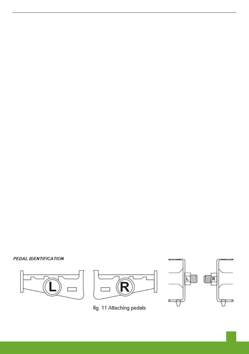
Step 4 Attachng Pedals(refer to fig. 11) :
1. The pedals are marked wth ether a “R” or “ L” on the threaded end of
the pedal axle.
2. Screw the pedal marked ”R” nto the rght sde of the crank assembly
(chan sde of electrc bcycles). Turn the pedal (by hand) n the clockwse
drecton. Tghten securely wth an adjustable wrench or the plate wrench
specal for pedals(Tghtenng torque: 34N.m or 26foot.lbs).
3. Screw the pedal marked “L” nto the left sde of the crank assemble.
Turn the left pedal (by hand) n the counterclockwse drecton. Tghten
securely wth an adjustable wrench or the plate wrench specal for
pedals(Tghtenng torque: 34N.m or 26foot.lbs).