As a policy of continual improvement, RMF reserves the right to alter the specification without prior notice.
201.028 REV 1 Date of Issue: 18 June 2018
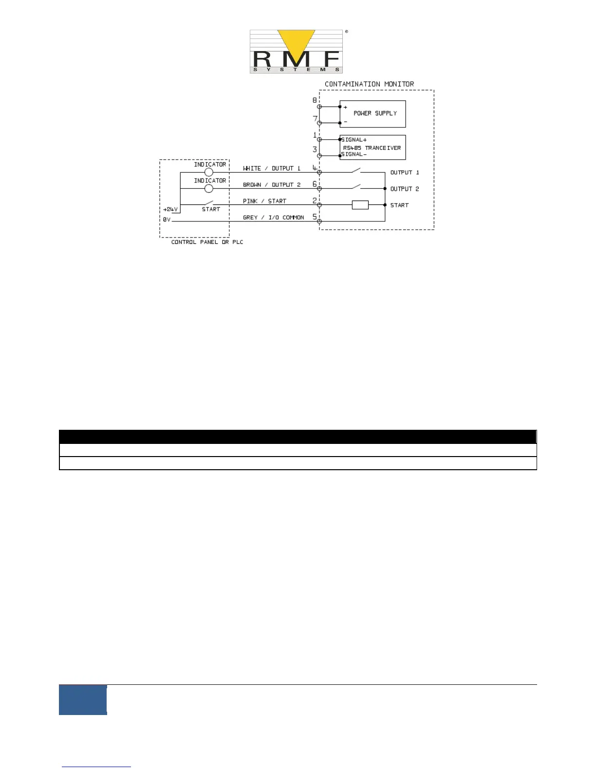
Figure 6.6 Switched I/O Signals
In order to reduce wiring the input and outputs all connect together on one side (see Figure 6.6). However they
are optically isolated from the rest of the system so can be used to switch unrelated signals.
6.1.2.5 Start Signal
The "start signal’’ is an opto-isolated input that can be used to start a test, it can be used to ensure testing only
occurs when the hydraulic system is running. For example, the start signal could be wired to go on and off with
the main hydraulic pump or with a solenoid valve that allows fluid flow. That way the log does not fill up with
invalid tests that were carried out with no flow.
This could be from a push button or a PLC output. The input accepts AC or DC signals, typically derived from the
DC supply voltage. The exact function of this input is determined by the Test Mode setting (section tbc).
− When the START signal transitions from OFF to ON, the unit will start a new test or restart any test in
progress.
− At the end of the test, the state of the START signal is checked
− If the START signal is still on at the end of a test, another test is started. So that testing continues while
the START signal is held on.
− The switching off of the start signal will operate as a STOP command. That is, it will abort any test in
progress. It will continue to show and report the previous result.
− This new operation mode applies whether or not continuous testing is enabled.
− So for example if "continuous testing" and "stop testing when clean" are both enabled, and if the start
signal is being held on throughout testing, then EITHER the start signal vanishing OR a clean result can
terminate testing.