201.028 REV 1 Date of Issue: 18 June 2018
Figure 6.11 Differential Pressure vs Fluid Viscosity, for various flow rates
6.1.3.2 Manual Flow Control
Another possibility is to fit a simple manual flow control (flow restrictor) to the outlet of the CMS.
− This should only be done where the available pressure is less than twice the maximum value calculated. This
is because the small orifice size needed to control the flow from a pressure larger than this has a risk of
blockage.
− The flow controller must be fitted to the outlet only. If fitted to the inlet it will have a filtering effect.
− The flow controller must be fitted directly to the CMS outlet port.
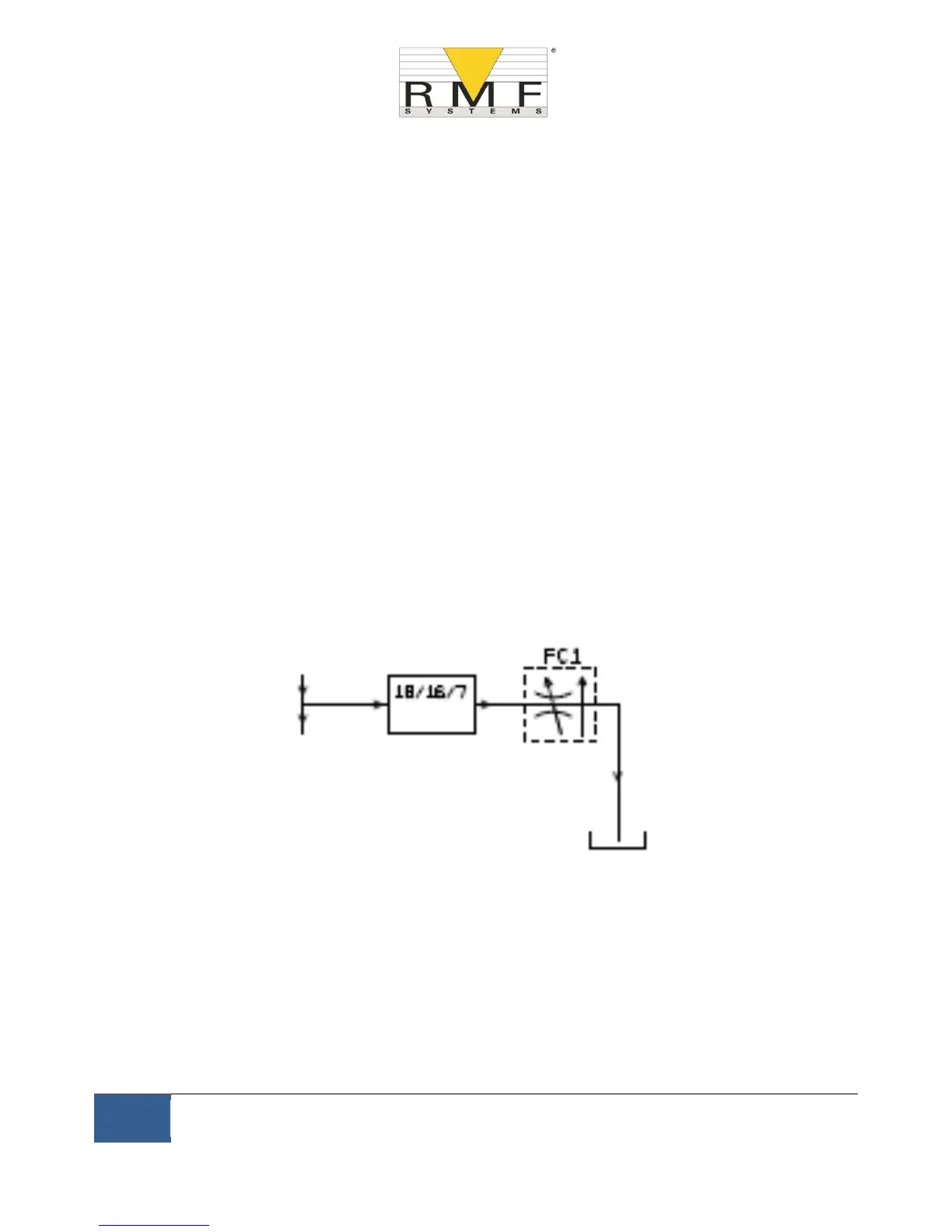
6.1.3.3 Active Flow Control
This is only needed for operation at high differential pressures, where a too-high flow would otherwise be
generated.
A pressure compensated flow control valve is fitted to the CMS drain outlet. This has the effect of a ``flow
limiter’’, maintaining a constant flow rate even with a varying inlet pressure (provided this pressure stays above a
minimum working value). Below this pressure the valve is wide open so has little effect, i.e. the flow will be less
than the 200ml/min controlled value. This ``minimum working value’’ will be typically 5-10 bar but will vary with
viscosity. For these lower pressures a flow control valve is not needed and other methods are better used to
control flow as previously described.
Figure 6.12 CMS flow actively regulated
6.2 General Operation
6.2.1 Physical Checks
• Oil leaks on and around the unit
• Fatigue in hoses and pipework that might then leak when under system pressure