(1) Tap end of crankshaft slightly to shoulder shaft against main bearing at flywheel end.
(2)
Use a depth gauge and straight edge to measure the distance between the machined surface
of the crankcase
(A)
and the crankshaft gear surface
(B).
Record this as measurement 1.
e
(3) Measure the distance between the machined face of the main bearing cover
(C)
and the outer
surface of the main bearing’s inner race
(D)
(EH30V
and EH34V).
For
EH43V, use outer surface
of boss for the plane metal bearing. Record this
as
dimension 2.
(4) The compressed thickness
of
the crankcase cover gasket
is
0.26mm (0.Olin.). Record this
as
dimension
3.
(5)
Subtract dimension 1 from dimension
2
and then add dimension
3.
The result will be the
final dimension. Choose an adjusting shim that is 0-0.2mm (0-0.008in.) less than the final
dimension.
(6)
Tap end of camshaft slightly to shoulder shaft against bearing in crankcase.
(7)
Use
a
depth gauge and straight edge to measure the distance between the machined surface
of the crankcase
(A)
and the camshaft thrust surface
(E).
Record this
as
measurement 4.
(8)
Measure the distance between the machined face of the main bearing cover
(C)
and the outer
surface of the cam bearing thrust
(F).
Record this as dimension
5.
(9)
Use the crankcase cover gasket dimension recorded earlier as dimension
3.
(10) Subtract dimension 4 from dimension
5.
Add dimension
3.
The result will be the final
dimension. Choose an adjusting shim that is 0.13-0.29mm (0.005-0.011in.) less than the finafl
dimension for
EH30V
and EH34V.
Choose an adjusting shim that
is
0.13-0.39mm (0.005-0.015in.l less than the final dimension
for EH43V.
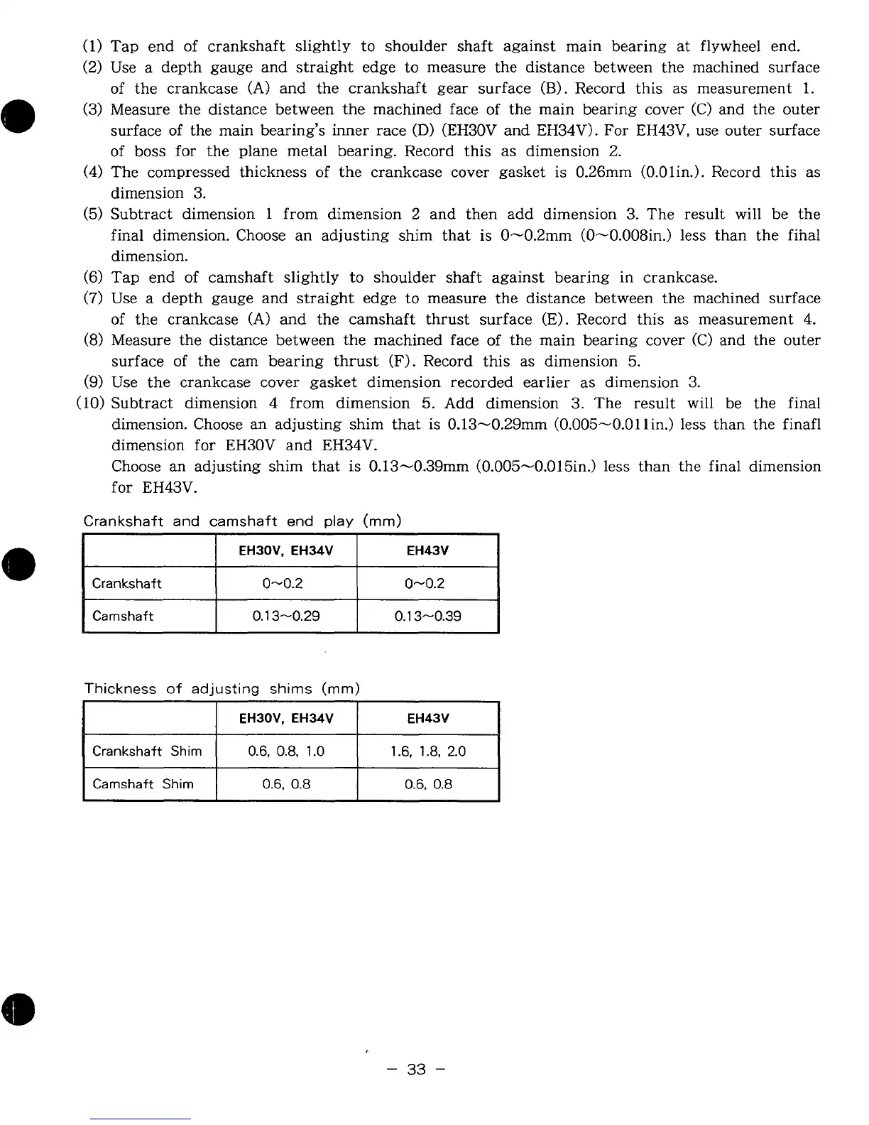
Crankshaft and camshaft end play
(mm)
I
I
EH30V, EH34V
I
EH43V
I
I
Crankshaft
1
0-0.2
Camshaft
0.1
3-0.39
0.1
3-0.29
Thickness
of
adjusting
shims
(rnm)
EH30V, EH34V EH43V
Crankshaft Shim
0.6,
0.8,
1.0
1.6.
1.8,
2.0
Camshaft Shim
0.6,
0.8
0.6,
0.8
-
33
-